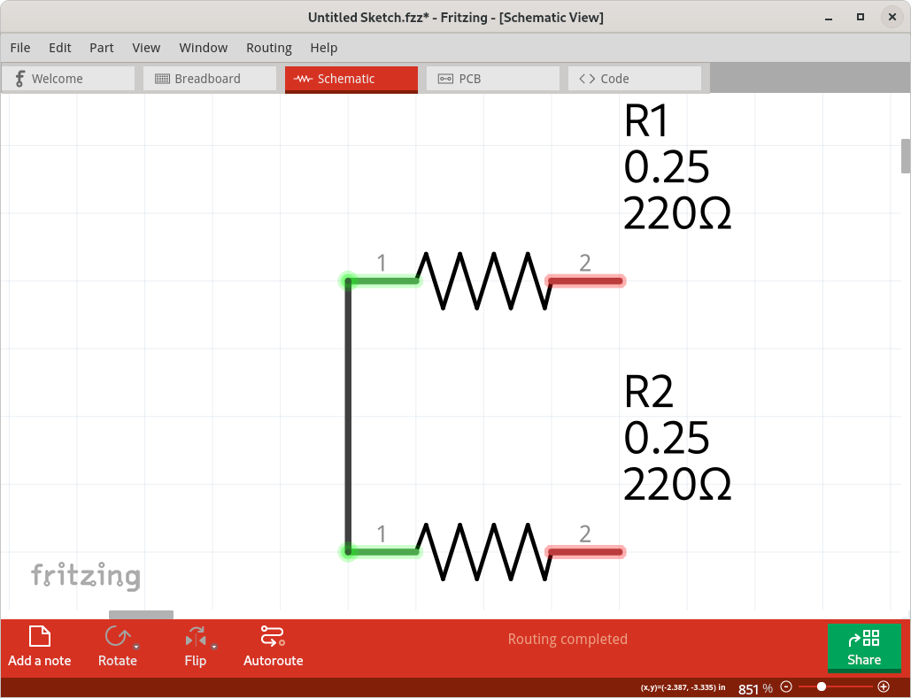
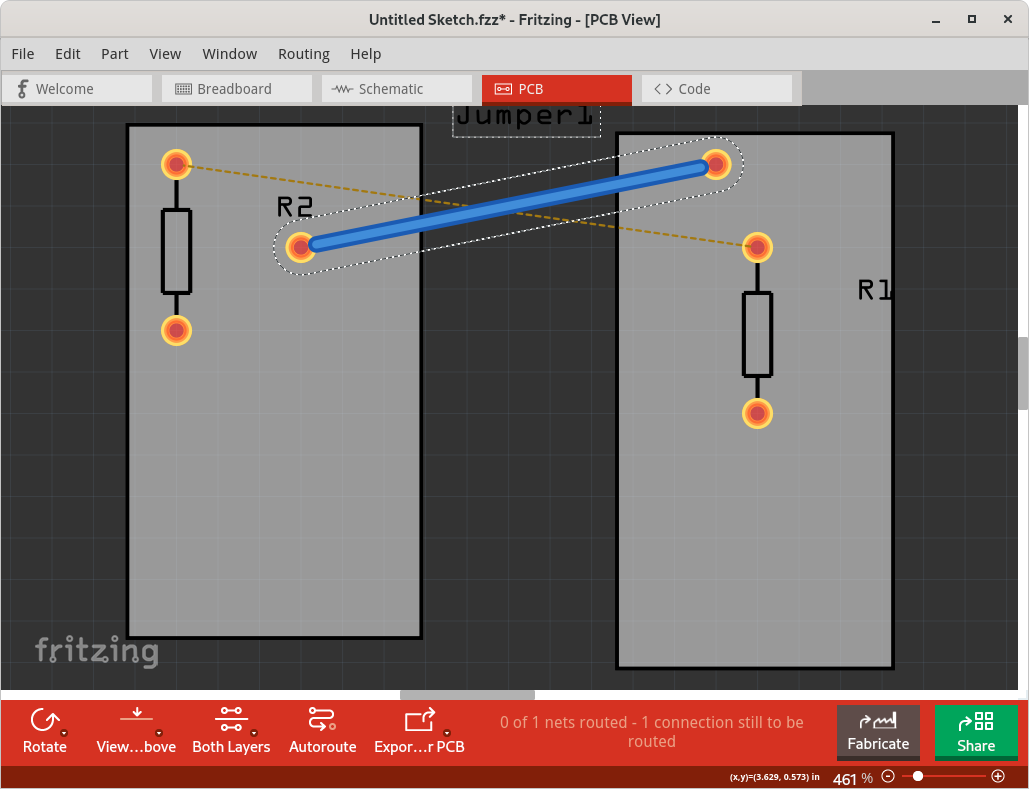
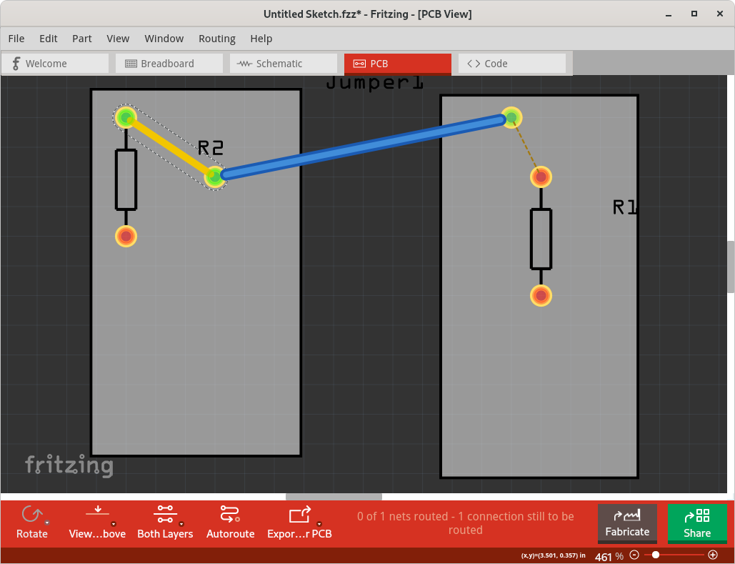
A dotted ratsnets line is shown everywhere that Fritzing believes that a wire is “needed”. To complete the circuit on the current view, to match what has been drawn on the other views. Which means it is anywhere that there is no ‘real’ connection between nodes (connections) that are in the same ‘net list’ after looking a the nodes and wires in the other views. A jumper placed by itself is not part of any of the existing net lists, so no ratsnest wires are draw to it. You need to connect one end of the jumper, with a real wire (pcb trace) to one of the other net lists. Then the jump becomes part of that net list, and the other end of the jumper will be used to continue the ratsnest connections. Below is a simple example. In Schematic view, I place a couple of resistors, and connected one end. In PCB view, I placed each of the resistors on a different pcb. That adds the ratsnest wire from the end of one resistor to the end of the other on the other pcb. The jumper is only on the PCB, not on the schematic (not on the breadboard either), and is not connected to anything. Drawing a trace from the end of the one resistor to the connector on the jumper merges the net lists, and the ratsnest line then move to the other end of the jumper, since that is not the short line to connect the final node of that net list.