Good afternoon! Can you please tell me what vias / connections are there in Fritzing for printed circuit boards in order to correctly draw dotted lines between two printed circuit boards? I have two PCBs in my project. Thank you in advance!
A dotted line (ratsnest wire) will show up automatically if either the breadboard or schematic view contains a wire connecting nodes that are on the different pcb. Ratsnest lines are always drawn ‘shortest path’, so the location will depend on the positions of the connectors that are part of that node list.
To create an actual connection between the boards, that can be positioned where you want, the “Jumper” part works. CORE bin, PCB View block of parts (3rd block from the bottom in Parts window).
Thanks for the answer! I added two “Jumpers” (one pin on one board and the other end on the other board), but these “Jumpers” didn’t get the auto-routed dotted lines that exist between the two PCBs.
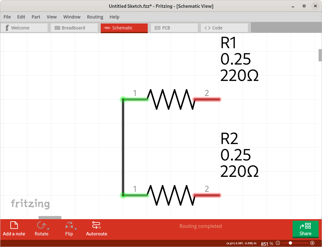
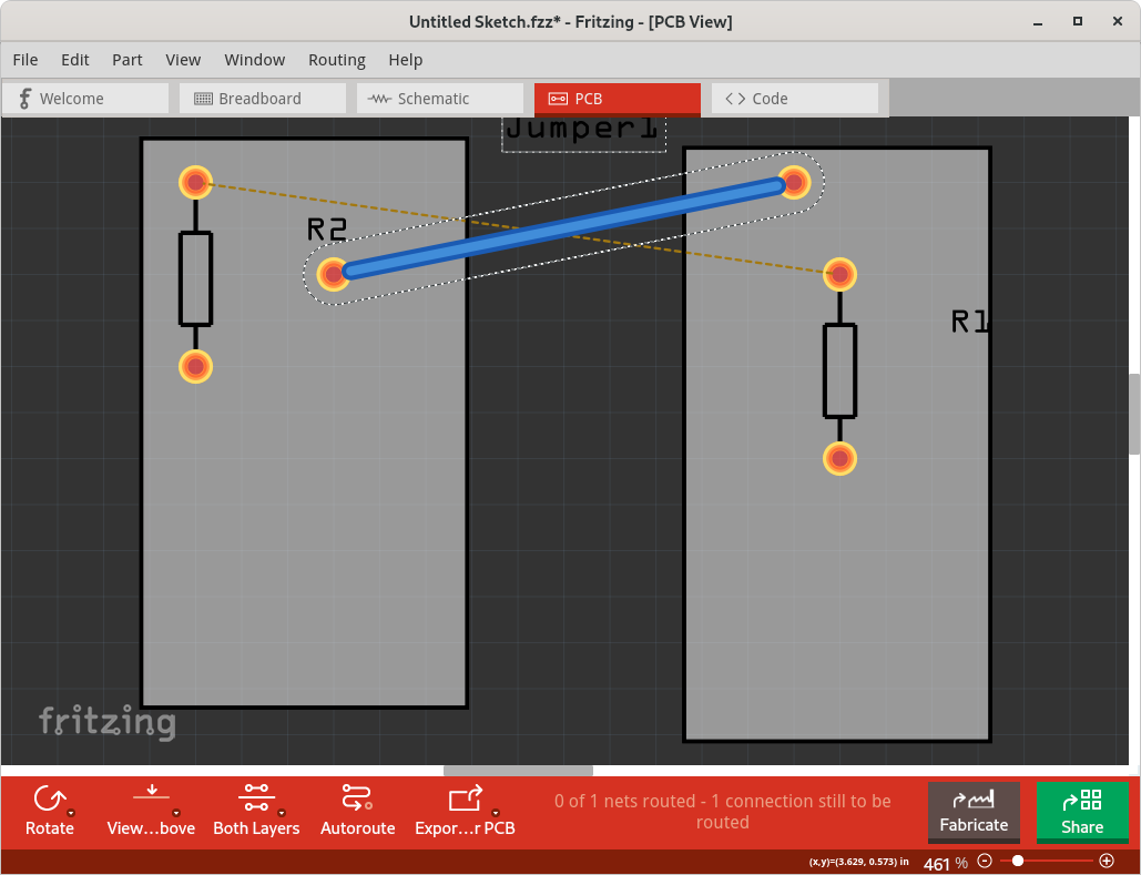
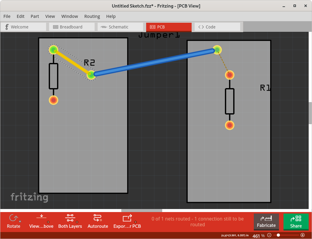
A dotted ratsnets line is shown everywhere that Fritzing believes that a wire is “needed”. To complete the circuit on the current view, to match what has been drawn on the other views. Which means it is anywhere that there is no ‘real’ connection between nodes (connections) that are in the same ‘net list’ after looking a the nodes and wires in the other views. A jumper placed by itself is not part of any of the existing net lists, so no ratsnest wires are draw to it. You need to connect one end of the jumper, with a real wire (pcb trace) to one of the other net lists. Then the jump becomes part of that net list, and the other end of the jumper will be used to continue the ratsnest connections. Below is a simple example. In Schematic view, I place a couple of resistors, and connected one end. In PCB view, I placed each of the resistors on a different pcb. That adds the ratsnest wire from the end of one resistor to the end of the other on the other pcb. The jumper is only on the PCB, not on the schematic (not on the breadboard either), and is not connected to anything. Drawing a trace from the end of the one resistor to the connector on the jumper merges the net lists, and the ratsnest line then move to the other end of the jumper, since that is not the short line to connect the final node of that net list.
Thanks! It’s great that the example with pictures! So it means that autorouting can’t add a Jumper element, and draw dashed lines through these elements?
Autorouting never draws dashed lines. It attempts to draw real lines to replace the existing dashed ratsnest lines. I don’t know if autorouting would create a jumper to complete a circuit. One either a single PCB, or between PCBs. I made no attempt to autoroute in my example. I seem to remember a case where it created a jumper on a single PCB, but that was a long time ago, and I could be remembering wrong. I don’t do a lot of pcb work, and do mostly manual routing. I found autorouting to be not very smart. It seems to use a fairly ineffiecent brute force search to find routes, and does not cleanup once a valid set of routes is found.
I use header pins and keep checking if they line up by grabbing 1 pcb and moving it over the other to make an arduino-shield-like sandwich.
Yes, great! And how do you find pin connectors and how do you check for these connections?
The header is a generic connector, you set the number of pins in Inspector
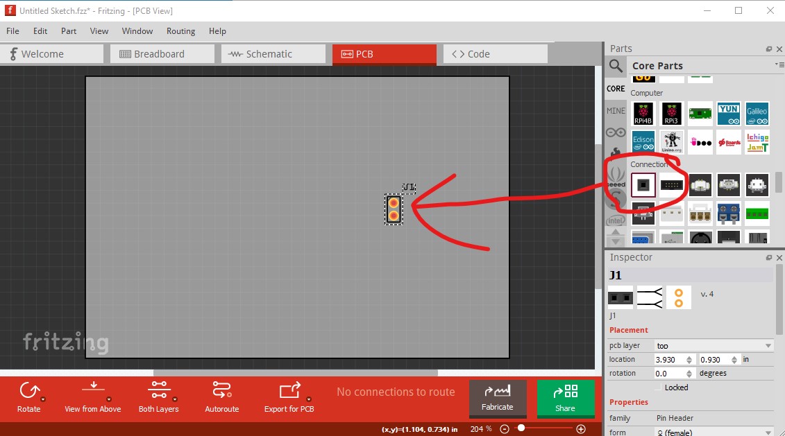
presumably you check the alignment by dragging one pcb over top of the other to make sure the pins align between the two boards.
Peter
Thanks, Peter! That’s what I was looking for
I have encountered a similar problem recently, and I am trying to solve it,there have very useful advice. I think I’ll try it