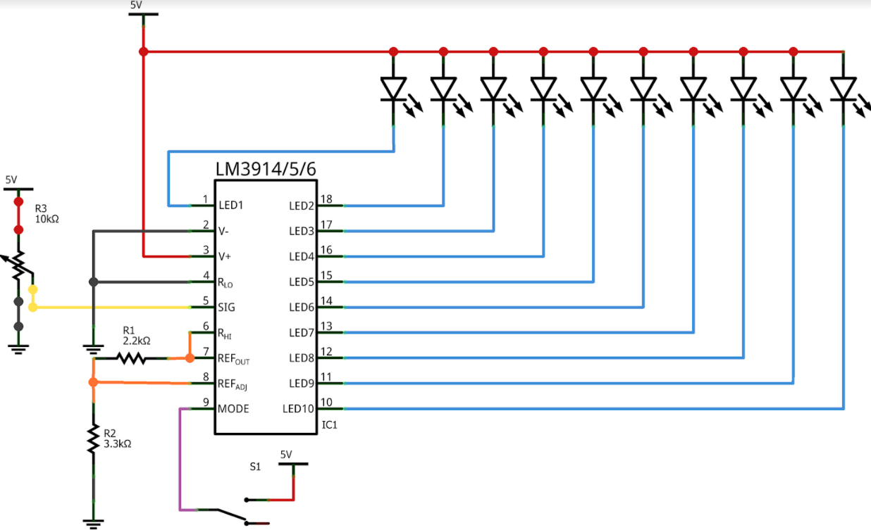
Hello guys, hope you all are doing great. I just have some doubts here. I was planning to make an audio indicator using an LM3915 ic. As from the circuit, we can see that pin 5 of the IC is connected to a 10kohm trimmer potentiometer (its function is to calibrate the circuit). Is it correct if I follow exactly the circuit? By connecting pin 5 to the wiper pin of the trimmer potentiometer. Or do I need to connect the wiper pin of the trimmer potentiometer to the voltage divider, which is at pin 8?
As shown the pot will adjust the input level of the audio signal, which is likely what you want to do. Changing the Vref circuit will change (possibly in a non linear manner) the threshold values of the comparitors. You would probably be best of changing the input signal level as the circuit currently does.
Peter
Hi Peter. Thank you for your precious advice ![]()
![]()