Hi
I thought I could connect the (-) cable to the esp GND, and then the (+) to the switch, and then to the esp VN. Is that right?
No. The Bat- to ground is fine, the bat+ needs to to the switch and from the other connector of switch to the VIN pin on the ESP32. VIN is the input voltage pin (7 to 12V) VN is a GPIO pin not a power pin. When you get this all finished it would be a good bet to post the result for review I expect.
Peter
Please upload the sketch (the .fzz file, upload is 7th icon from the left in the rely menu) you are likely not connecting to the terminal on the switch but I can’t tell from an image (.fzz files are always a better bet when you have an issue!)
Peter
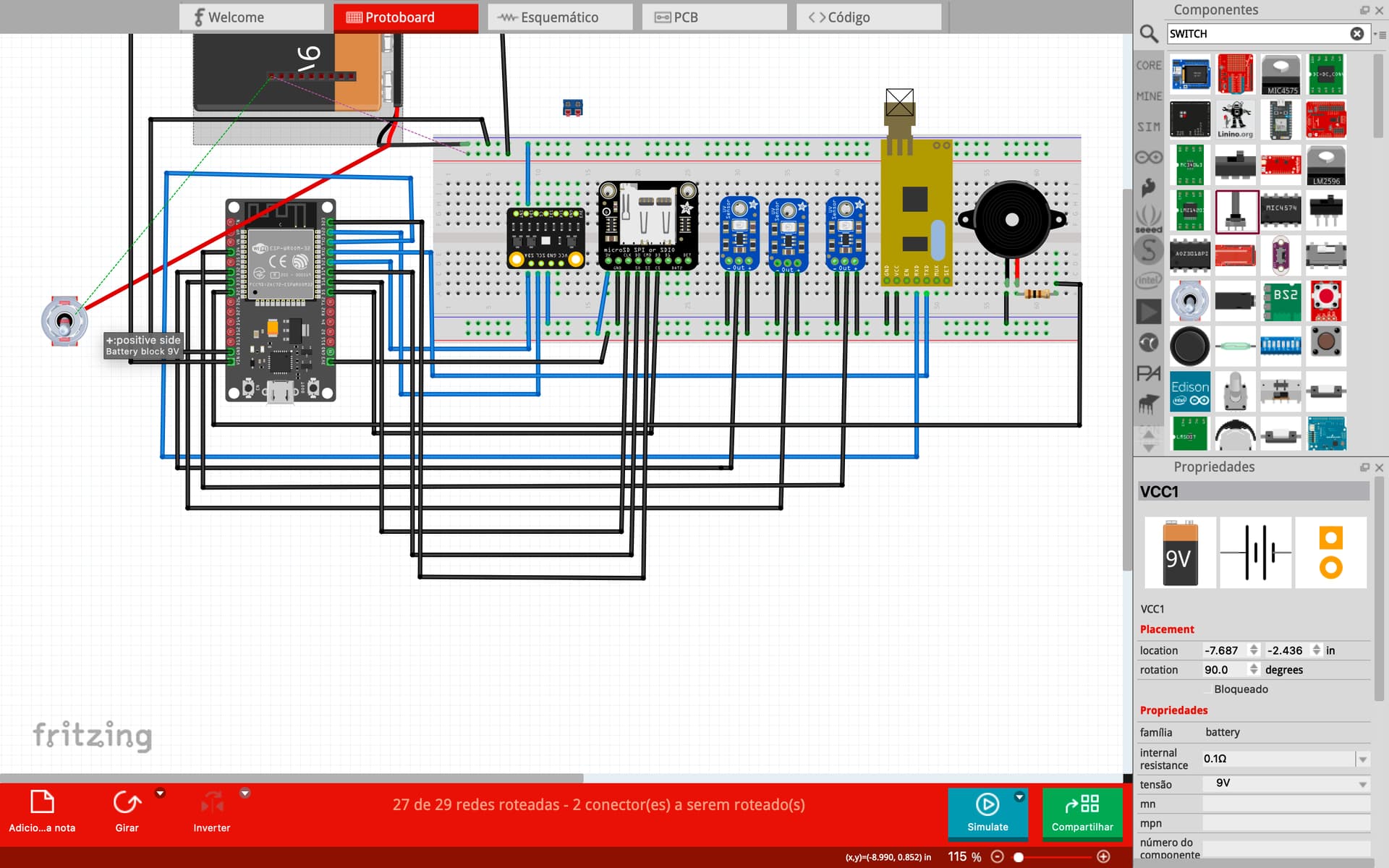
cansat ultimo.fzz (103.1 KB)
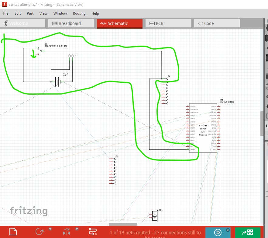
Your switch is wired wrong. Here I routed the traces in schematic to see where the connections go (much easier to see than breadboard!)
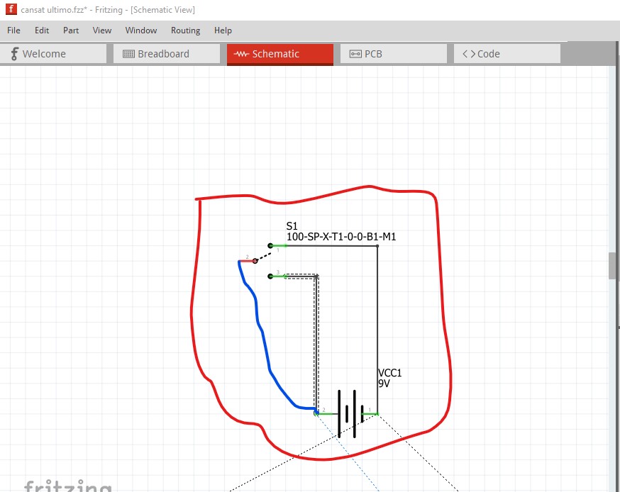
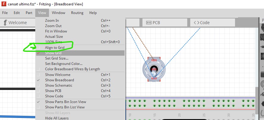
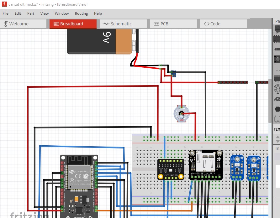
The switch will currently do nothing as it has no connection to the common pin. If you added the correct connection (the blue wire) to the battery you would short the battery when closing the switch which is not what you want. The first thing to do is enable align to grid so the parts align to the grid in breadboard (after doing this you need to move all the parts to cause them to snap to the grid!) That makes your breadboard much neater.
from this:
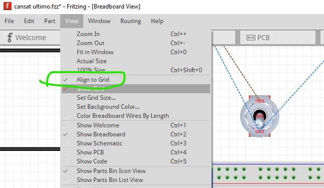
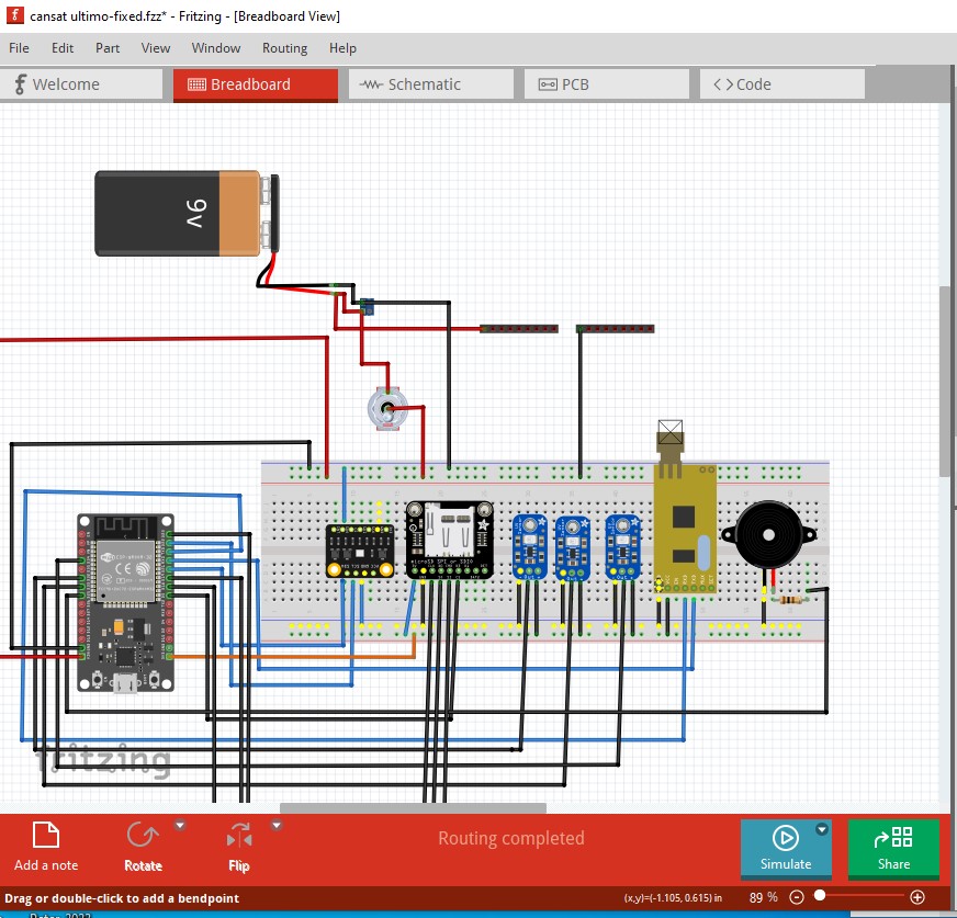
to this:
then you need to determine which pin is which on the switch. To do that hover over a connection and Fritzing will display the pin name (here the common pin which you want to connect to the positive side of the battery so the switch will work is at the end of the green arrow.)
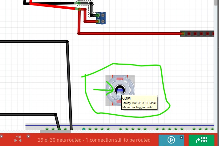
then change the connections to be correct. The battery connects to the screw terminal (in practice it is the other way around, the battery, off board will connect to the screw terminals to get the battery on board.) From there the positive goes to the NC contact on the switch and the common of the switch goes to the VIN pin on the ESP32. Now operating the switch will turn the power on and off as intended.
and in schematic things are now correct.
These changes are in this sketch
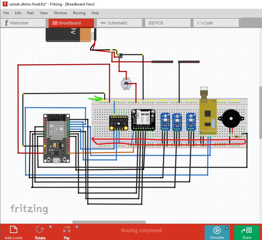
cansat ultimo-fixed.fzz (105.3 KB)
Changing the wire colors in breadboard will help you keep the wires more correct I expect. Use black for ground and red for power in and perhaps orange for 3.3V to tell them apart at a glance. Use the same color for all common connections so you can easily see where they go. Route schematic so you can see the connections are as you expect them to be.
Peter
thanks! What is the use of those pins? btw can you check on the antenna and if the GND of the sensors are actually connected to the esp GND? please
Assuming you mean the switch, the com pin is common and connects the com pin to the NO (normally open) and NC (normally closed) pins. Moving the switch lever moves the connection from NC to NO (or the reverse.) You need a connection to the com pin for the switch to work.
You can do this for yourself. Click on any pin in the ground connection and it will light everything connected in yellow like this
which indicates you have a break in the top and bottom ground connections which means this won’t work. The antenna is internal to the part and has no external connection.
Peter