Ah! Turns out this is my fault. There is an error in the part. I just uploaded a corrected part to the original post, so if you download the part again and replace it by doing a delete minus on the current part (which will leave the traces) then load the new part (which will load because of a new moduleId)
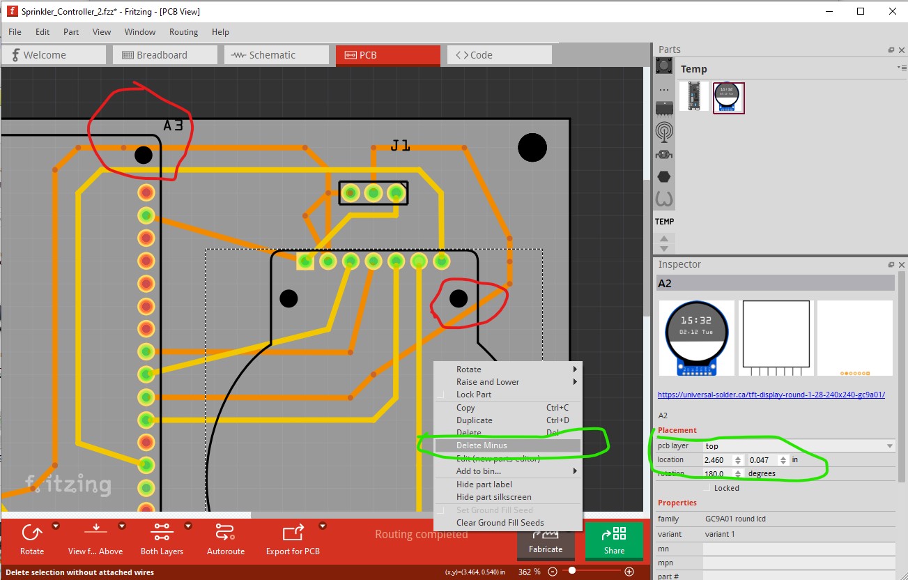
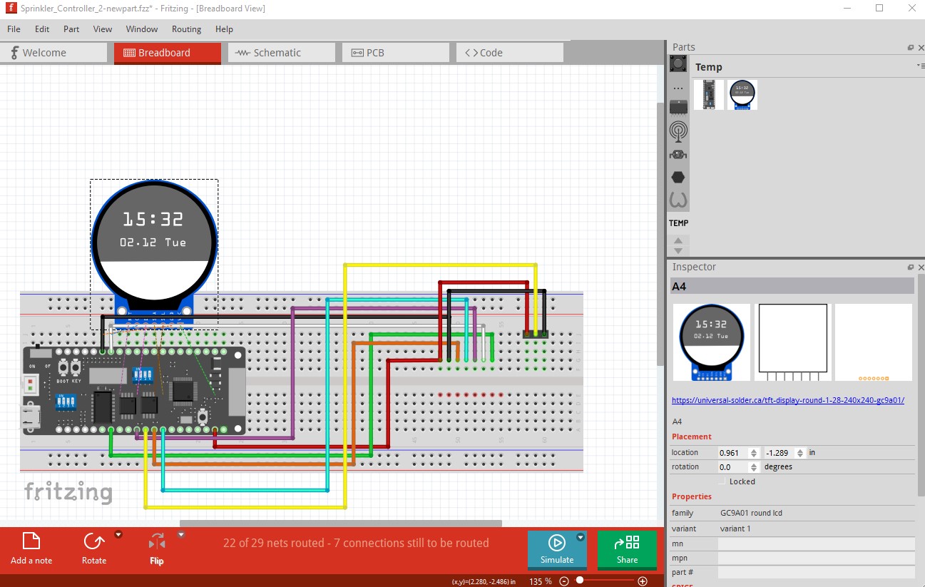
then in all views drag the the new part in to position and attache the wires like this. First right click on the display and select delete minus to delete the part but leave the traces. Make note of the xy position of the part in Inspector (the lower right window) so you can place the new part accurately.
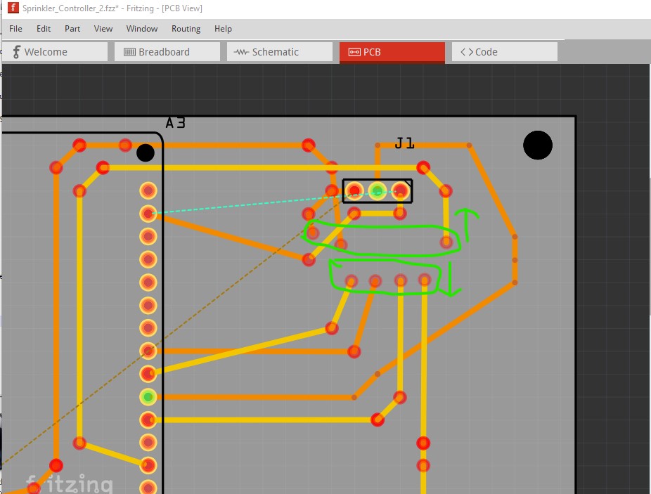
then in pcb view move the top traces up a bit and the bottom traces down a bit (this can get complex with overlapping traces though and some times it is easier to just rewire!)
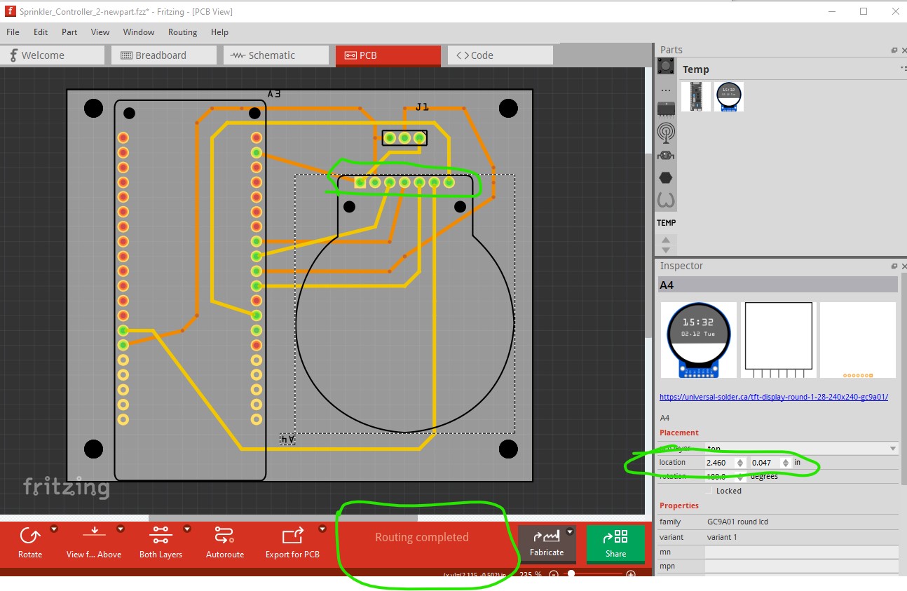
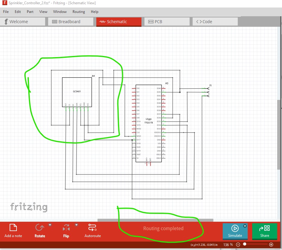
in this case though it works all the connections are green, and the display is at the same x/y coords it started at so all should be well.
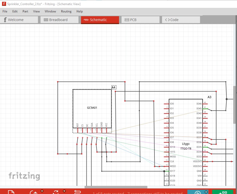
Now on to schematic view move the new part to near the old connection point (rotating the part if necessary) then drag the wires til they connect.
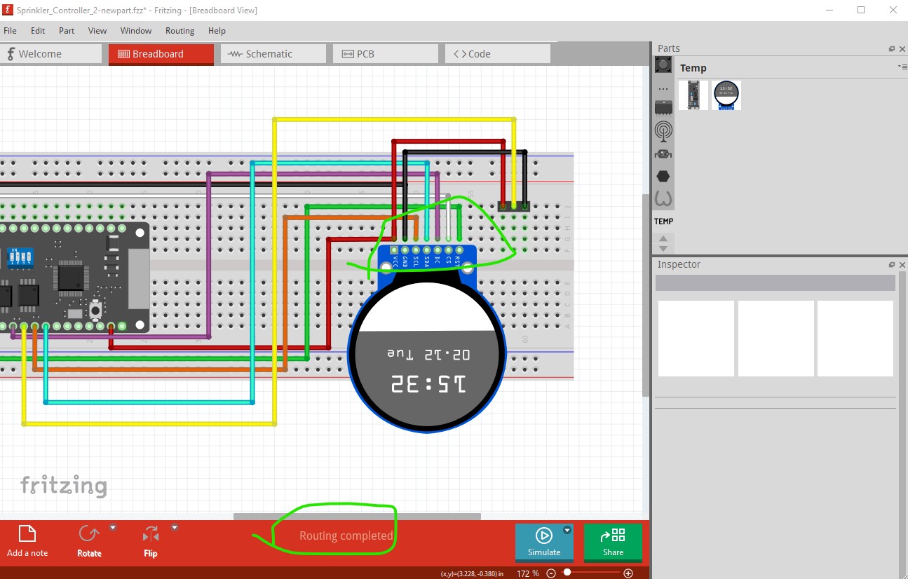
then do the same in breadboard (here you do need to rotate the part 180 degrees to make it line up)
then position it correctly and move it up until the pins connect completing the sketch
this is all in this sketch (which has the new part loaded.) You can try all this for your self or just use the corrected sketch.
Sprinkler_Controller_2-newpart.fzz (94.8 KB)
where the export of etchables now works correctly
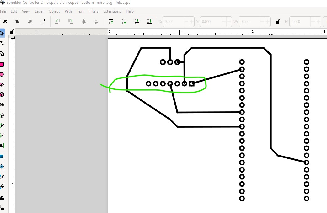
due to the correction in the part.
Peter