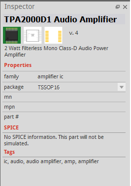
Also if it helps. I made this component based off of the TPA2000D1 Audio Amplifier chip that was already in the Fritzing library.
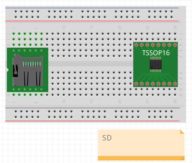
An image is not enough to be sure, but I expect the problem is that the connector are not configured as type=“male” in the fzp file. Searching for “TPA2000” in the core finds 3 parts. 2 of them connect to the breadboard, the third does not. I expect that you used that 3rd part as the base for your part. The connectors there are marked as type=“pad”, which will not connect to the breadboard. “pad” should only be used for raw SMD parts. A carrier board like this appears to be should use “male”.
An SMD part can use type=“male” to allow the carrier board to connect on breadboard view, and still use the raw SMD footprint for the PCB view. That combination allows breadboarding with carrier board, and still using the bare chip for PCB.
Thank you! Changing the pin types to male worked.