since I’m used to the MB102 breadboard for a long time and using it for
the electronic lessons to 7th-11th graders I’d like to use fritzing now for
demonstrating good placement to a larger group of people.
However, I couldn’t manage to place NPN, LED and two resistors as I’m used to.
+++++++++++++++++++++R1+++++++++++++++++++++++++
                    hole
                    hole
                     R1
                    hole
                    LED+
========================================
                    LED-  hole   hole
                     C     B      E
    R3               R3   hole   hole
                    hole  hole   hole
           R2       hole   R2    wire
---------------------------------wire------
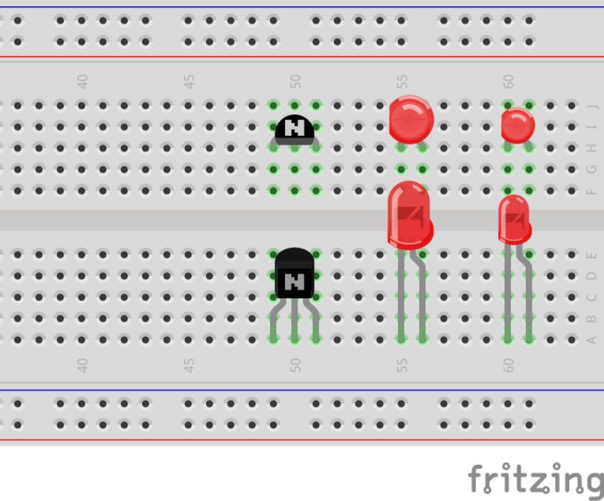
The sketch above is one part of a bistable FlipFlop, where the other part looks the same
and is on the left side (unshown here). R3 connects then to the other NPN-Base.
I like this placement of parts, because the three rows of holes below the NPN are comfortable for
cross-wiring other components e.g. capacitors for the astable multivibrator.
This sketch is very compact and is using only one wire for Emitter to GND.
However, I’m not able to use Fritzing to realize such a placement…
Does anybody know how i could resolve this feature ? Or is my wish impossible ?
I do have trouble thinking - head is always muddled -, and I don’t know if it’s people not writing sentences properly anymore, because most of the time I just don’t get it.
This is In the wishlist but he says “However, I’m not able to use Fritzing to realize such a placement. Does anybody know how I could resolve this feature ?”, which doesn’t sound like a added wishlist feature. Then further down someone is talking about obscured parts.
I read it again, and maybe 3 more times, does this guy want a more vertical view in BB, because I can’t find anywhere where there is a statement directly asking for a feature.
This is all a moot point as it’s 6mths old, but I don’t really know what he is still interested.
My original post was really about the top view of the breadboard and
a vertical view of some components such as LED and NPN in order to
get enough space for Rs and Cs and their wiring in the lower three rows.
If my students don’t get any hints how to put components the best way,
they do sometimes a chaotic placement and then is very difficult to find
any wiring error in time…
If NPNs and LEDs get the same position on the 15 breadboards of my students,
then it is much easier to assist them.
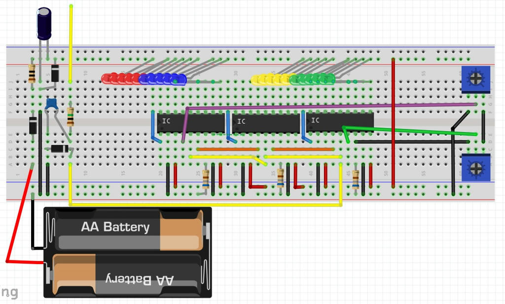
Even thought it wasn’t directly stated that’s what I guessed you wanted. You just have to change the breadboard part svg so it’s looking directly down, which Steel is probably doing, but even then parts still kind-of get in the way. Have you ever put 30 5mm LEDs vertical in a row straddling a break and using all pins without a break. http://www.mediafire.com/convkey/3f62/4sbprm8b0ozcnyy6g.jpg
I would have though 2 or 3 small squares on top of the part would be better because it would be more real, but then again red contacts wouldn’t be seen on a red LED. Does the part obscure the pins if they are on top.
The bendable legs are FZ generated legs. They are generated on top of the image… it looks like they are coming out of the top of the image… There was no way around this… Try dragging one of the bendable legs across the image, they will always be on top… If you want the legs underneath, try dragging the legs under the image when off the breadboard then drag the image on the the breadboard…

