Hello everyone,
To start I’m actually a beginner with this.
I created an pretty basic PCB board.
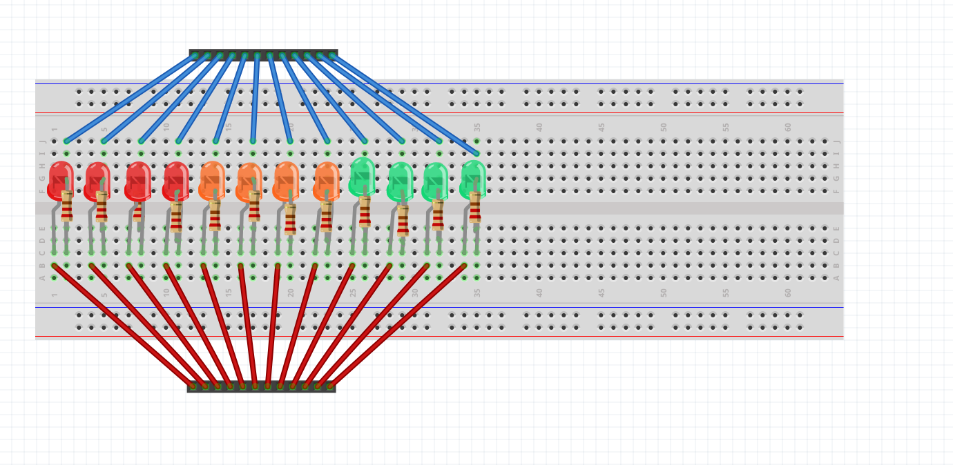
At first I have 12 female headers connected to 12 leds. This is used to connect a wire from my Arduino Uno to my PCB so I can control every led. Then to cathode side of the led a 220 ohm resistor.
The resistor is connected to a header wich will be connected to the ground. (just for exploring this programm)
But I want to use a common ground, so I can connect 1 wire to the ground of my Arduino and all of the resistors are connected to the ground.
I guess I need to use a ground layer (i don`t know how to do that with this programm.)
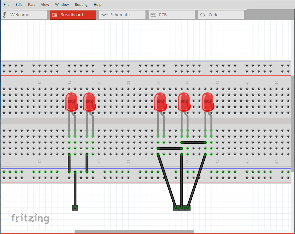
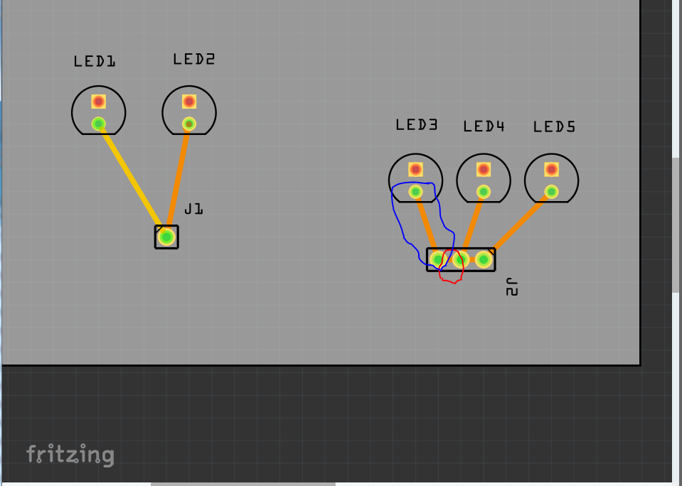
Here are two ways to do this, the first (with 2 LEDs and showing only the ground connection, because I am lazy ) assumes you want a single ground pin connection which is usually all you need. The second with 3 LEDs assumes you want a ground pin for each LED for some reason, and they are therefore all shorted together to make a common ground:
Note each LED ground has two connections, one the the LED (outlined in blue) and one to the next pin on the connector (outlined in red.) Connecting a wire to any of the ground pins (but only one at a time, more than one may cause a ground loop) is sufficient which is why the single pin version is more common. The 3 LED version would usually be because you have two or more Arduinos driving the LEDs and they need a common ground.
 ) assumes you want a single ground pin connection which is usually all you need. The second with 3 LEDs assumes you want a ground pin for each LED for some reason, and they are therefore all shorted together to make a common ground: