Please add this new microcontroller board.CloudX Fritzing New.fzpz (42.3 KB)
Your part has a number of problems:
It isn’t aligned to the grids properly, The pin numbering isn’t in order, pcb is not correct, schematic doesn’t have correct terminalIds which causes this (the lack of a terminalId in the correct place causes the connection in the middle of the pin):
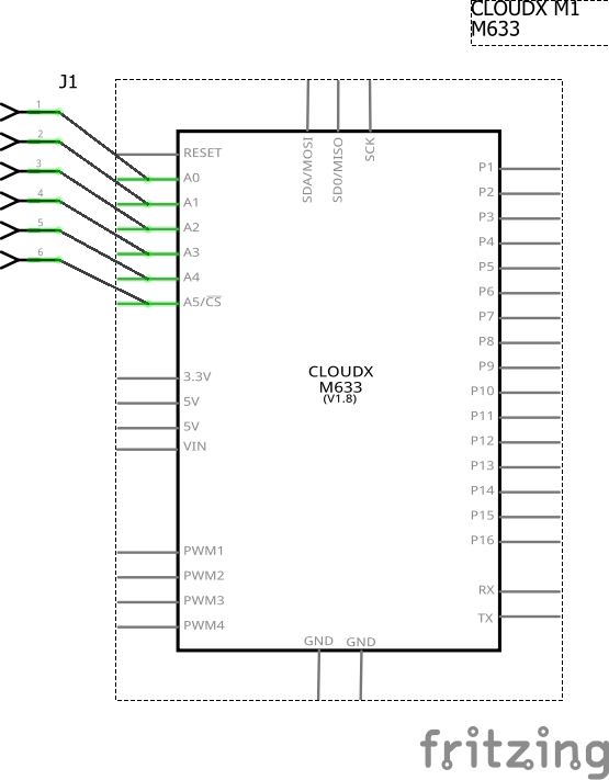
As well the pin numbering is in random order. I can fix all of those up for you if you like, but as I would prefer to renumber the pins in to a sensible order, that will break any sketches that use your current part. If there aren’t a lot of sketches that need to change that would be my preferred course forward. If there are sketches using this part it is possible (if less than desireable) to keep the current pin layout. As well assuming you want this included in core parts, you would need to submit a pull request on github. Parts posted here no longer get moved in to core (although that may change with the new development effort that is starting.)
Peter
1 Like
Thank you Peter, we would appreciate if you can make necessary fixing to this part.
OK, I’ll have at it, I take it you don’t have a large number of sketches using the part so you won’t mind if I change the pin numbering (which will break your current sketches)? Since you have Eagle files for the board I may just start from scratch with EagletoFritzing as that should generate the correct layouts.
Peter
1 Like
OK here is a fixed up part. I started again by running your eagle .brd file through eagle2fritzing to get the (hopefully) correct layouts and then fixed that up. Things to note: I changed schematic to match breadboard because I find that easier to use when trouble shooting. If you would rather have the power on top, ground on the bottom layout feel free to change schematic. The VCC group on the top and bottom pins doesn’t connect to a power source, if it should connect to 5V or 3.3V you (or I) would need to change the bus configuration in the fzp file. The bus configuration connects pins that are common, for instance if you click on the TX pin the TX pin on the top 6 pin connector will light up yellow to indicate it is common.
Edit: Replaced this with a corrected version that changes the CPU in breadboard to a PIC16F877 rather than the Amtel Eagle2Fritzing chose, and corrected the two VCC pins to be 5V and part of the 5V bus as they should be. If you have downloaded this part please download the new version to replace it.
CloudX Fritzing New-fixed.fzpz (34.1 KB)
Peter
1 Like
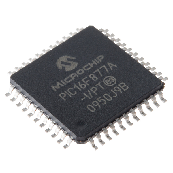
Hi peter, i really appreciate your effort on our CloudX fritzing part, my team has tested the new design you made and it is really cool. we noticed you put ATMEL on the microcontroller instead of PIC from Microchip technology.
Check this image for the design on the chip: PIC16F877A
Thanks to the Fritzing community:+1:
From ByteHub Embedded Team
That must be an issue in eagle2fritzing. I just checked the Eagle .brd file on your website that I built the part from and it indicates the CPU is PIC16F877PT. Somehow Eagle2Fritzing decided it was an amtel part. I’ve corrected that and changed the two VCC labels to 5V to match the rest (since I see that is what VCC is internally) and add them to the 5V bus rather than a separate VCC bus and have replaced the board above with a new one with the corrections. It would be a good bet to check the orientation of the ISP and whatever the top connector is. The pins are what eagle thought they were so should in theory be correct and correctly oriented, but a check against a real board is the best bet in case I got something wrong again.
Peter
1 Like
Thank you peter, my team and I will review the changes you made and reply you as soon as possible.
Good work to the fritzing community.
Why did it ‘decide’ it was an Atmel part?
Answer: Because Microchip bought Atmel and is now the source for Atmel & Pic chips.
1 Like
hi peter, we’ve checked on the part fixed and it really look so awesome.
Great, if you are happy with it, to get it in to core parts you need to make a pull request against the nightly-parts branch on the parts repository on github
As far a I know (for at least the last couple of years) parts only posted here are no longer being included in core parts.
Peter
1 Like
While I’d like to think someone was maintaining Eagle2Fritzing that well, I suspect it is more likely a bug … I did use Adafruit’s version which is being somewhat maintained so I guess it is possible.
Peter
Please help me to convert this CloudX Priscilla Mini svg file to Fritzing

Check Picture Here: CloudX Priscilla
That is easy enough to do, but this svg has a few issues:
it is slightly skewed in X. A vertical line starting at the edge of the white space on the RST connector is slightly in to the tan by the SCL connector. However the top connector is not skewed in y, which will cause a problem as it will skew as the X skew is removed changing its position.
The VCC connector below SCL is offset from the center of the SCL connector when I would expect them to align (they may not in real life which would be fine)
The scale is incorrect, i.e. the y spacing from the rst pin to A0 is 0.0365 in in x rather than 0.1 in
The connectors on the top 6pin header are 0.345 inches in y rather than .1 inch.
If this is the only data available all those things can be corrected in Inkscape with some work, but if an eagle brd file is available, a run through Eagle2Fritzing will generate all the needed files more easily. Is it possible to get an eagle .brd file for the board? If the SVG is the only thing available, then dimensions of the board and x.y position of at least one pin of each connector would be needed to correctly position them.
Peter
OK, here is a part. Since your graphic artist is much better than either eagle2fritzing or me I copied most of their work in to eagle2fritzings breadboard. Of note is that Eagle2fritzing thinks the PGD pin also connects to P8 and the PGC pin connects to P7 so they are bused together. Worth verifying that they should be bused together.
cloudx-priscilla-micro.fzpz (57.2 KB)
If the micro board is same pinout (with just different chip) then this part will do for both. If they pinout is different then the mini would need a new part.
Peter
1 Like
Thank you, i will review it soon.