LM1800 is an integrated FM stereo demodulator IC which has a number of good features integrated on it which makes it possible to design a high quality FM stereo demodulator system with excellent sound quality. The LM 1800 uses phase locked loop technology to regenerate the 38kHz sub carrier from the composite signal. The features of LM 1800 are automatic stereo/mono switching, wide power supply voltage range, good channel separation, excellent power supply rejection, no coils required, tuning can be done using a POT etc.
Description:
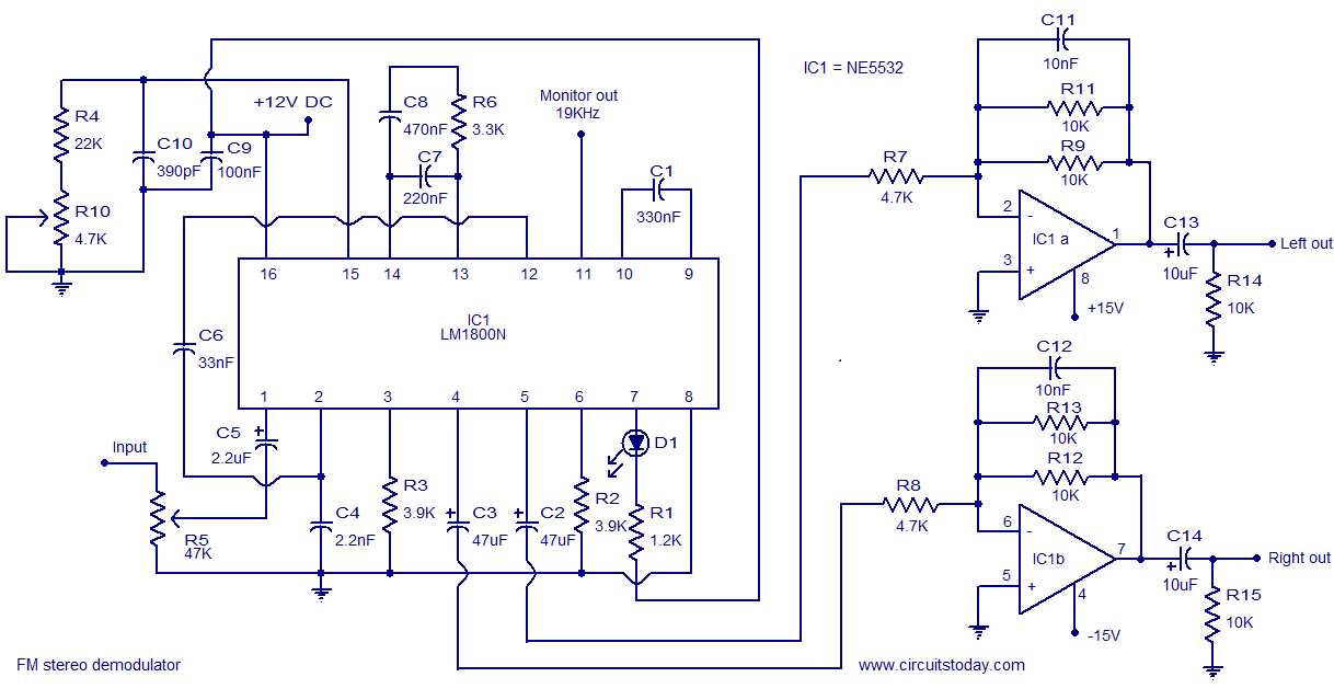
A very simple and high quality FM stereo demodulator circuit using LM1800 is shown here. Composite input signal is applied to pin1 of the IC through POT R5 and capacitor C5. C5 is a DC decoupling capacitor. R5 can be used to adjust the input signal level. The output of the internal audio amplifier circuit (Pin2) is coupled to the phase detector input through capacitor C6. Capacitors C8, C7 and resistor R6 forms a filter network. Pin 15 is the control terminal of the 70kHz internal voltage controlled oscillator. The required tuning voltage is given to this pin using Resistor R4 & POT R10. Tuning can be performed by adjusting the POT R10. LED D1 is an indicator LED and R1 is its current limiting resistor. C1 is the threshold filter capacitor. Pin 11 is the pilot monitor output pin. Supply voltage ie, 12V DC is applied to pin 16 of the IC. C4 is a noise bypass capacitor for the internal audio amplifier’s output. Right and left audio outputs are available at pins 5&4 of the LM1800.
Next stage of the circuit is a 2 channel driver storage based on NE5532 IC. NE5532 is a dual, internally compensated, low noise op-amp suitable for audio applications. First op-amp inside the NE5532 is used for amplifying the left channel and the second op-amp inside the NE5532 is used for amplifying the right channel. Both of them are wired in the inverting mode with a gain of around 4. R14 & R15 are load resistors. C2 & C3 are DC decoupling capacitors. The left & right load/de-emphasis pins (pins 3 &6) are grounded using 3.9K resistors (resistors R3 & R2). C11 & C12 are feedback capacitors. C13 & C14 are output DC decoupling capacitors.
Circuit Diagram
Notes.
Assemble the circuit in a good quality PCB.
Use 12VDC for powering LM1800N
Use +15V / -15V DC for powering NE5532.
POT R5 can be used to adjust the input signal level.
POT R10 can be used for tuning.
The power supplies must be well regulated and ripple free.
Use IC bases for mounting LM1800N & NE5532.
Input must be applied with respect to the ground.
