I am trying to replicate a project found on youtube https://www.youtube.com/watch?v=Ixln9wI0_uQ
It is similar to what I need but there is no clear circuit diagram.
i want to set it up on breadboard and then adjust code to my needs. Teaching myself both arduino and fritzing on something of interest to me rather than trying to absorb information from 50 odd tutorials.
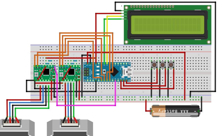
From the limited visuals on the video, I have tried to duplicate it in fritzing.
I will try to upload a picture of what I have created on fritzing, please ignore the battery powering it, I intend to use 12v dc 3 amp power supply.
It will be easier to help if you upload the sketch file (the .fzz file.) Upload (as you have probably found) is the 7th icon from the left in the reply menu. There are also a number of power supply parts available in the forums (not yet in core parts though) this one is one instance:
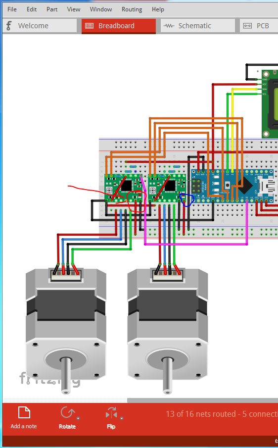
That will depend on the stepper motors. The ones currently in the drawing indicate they need 15V on the Vmot pin of the motor driver (the Vmot pin provides the power to the stepper motors and unlike the rest of the circuit can be larger than 5V.) You will need a power supply capable of providing both the voltage and the current the stepper motors need (and you need to read the data sheet for the specific stepper motor to find out what it needs.) There is a wiring error in your circuit. The first motor driver (pins circled in red) has ground and Vmot reversed which is likely to damage the stepper driver. The Vmot pin (circled in blue on the right most motor driver) can be connected to a higher voltage than 5V, but the rest of the pins are 5V maximum.
Thank you again, the 2 steppers I have are below. Am I right in guessing it would run on 5v (2.2v each) and it would need 4 amps (2 amps each)
I have ordered a Lab power supply with digital voltage regulator, so will be able to set exactly to what I need initially.
Thank you for pointing out the reversed wiring mistake.
Regarding the vmot 5v , does that mean if I do use 12v supply (where battery is) the nano and lcd cannot be connected to the common live rail at the bottom.
Sorry for all the questions, just trying to grasp it.
While I’m not an expert on stepper motors, I’d expect they really want 2.2V not 5V. They will try and draw around 4A at 5V and that may damage the motors. Also the stepper driver likely won’t provide even 2A. It notes it wants a heat sink to provide 2A and this article from the Pololu forums recommends against doing it. There are higher current motor drivers available, but I would think you would be better off with a higher voltage motor (which will draw less current for the same torque I believe)
Yes, the nano and the motor drivers (other than the Vmot pin), need to see 5V max, so you would need a regulator to reduce the 12V down to 5V to run the logic. The 12V then connects to Vmot to power the motor.
Not a problem, I have had to ask many such questions over the years, and am now paying forward others assistance to me I think you may want to find a stepper motor specific forum of some kind, to get answers from people with practical experience using stepper motors. I know the theory but am short on practice and at least at high speeds it is a complex problem (or used to be 40 years ago, when last I was involved in stepper motors )
Thanks again for your help. I have successfully run both steppers with a simple sketch just to test the components. It did not work initially until I added a jumper across reset and sleep pins on both the A4988 drivers. Just one thing I do not understand. Why would this circuit need jumpers between ms1-ms2 ms2-ms3 on the drivers. I’m thinking of getting a ‘buck converter’ for 5v supply to allow it run on just a single 12v supply without the nano connected by usb.
These two are likely related. I’d guess (without having looked at the driver schematic assuming it is available) that the pins don’t have internal pull up resistors or the pull ups are set to be disabled (reset and/or sleep asserted) if not connected. If you don’t connect them to a pin on the micro or a resistor or jumper to power or ground (which ever they need to work) the motor won’t run. The 3 ms pins set the microstepping mode you want, and again need to be either driven from the micro (if you want to change the microstep configuration from your program) or be tied high or low to set the microstep config you want. You may want to (carefully because it may be hot enough to burn!) check the temperature of the A4988 when the motors are running. I remember seeing something about current limiting, so it may protect itself, but it may not too (and burn out if it is taking too much current.)
So therefore the jumpers are set high to allow sixteenth steps, makes sense to allow more precision.
I did some research on the A4988 driver and set the pot Vref to 0.72v on both drivers.
The drivers did feel hot to the touch but I believe they do run hot and I have not stuck the little alloy heatsink on yet. The motors were cool but then again they had no load, just programmed both to turn 5 times clockwise then 5 times in reverse at the same time.
Was drawing less than 0.5 amps according to my adjustable desktop power supply.
That sounds fine, at .5A I expect the A4988 will be happy. The heat issue may come when there is load on the motors and they start drawing more current. Depending on how much load is on the motors, you may be fine as is. If you get up to the 1.5 or 2A current range with load on the motors you may need the heat sinks or forced air cooling. Sounds like you have things in hand , if you have more questions feel free to ask.
 , if you have more questions feel free to ask.