Hello all,
I wanted to make a PCB to mount on another PCB. For that I wanted to use castellated holes. Is there any way to do this in fritzing ?
Thanks
This is what I am talking about-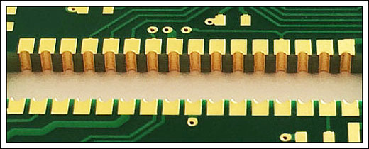
Hello all,
I wanted to make a PCB to mount on another PCB. For that I wanted to use castellated holes. Is there any way to do this in fritzing ?
Thanks
This is what I am talking about-
I am not aware of anyway you can do this in Fritzing because Fritzing does not allow holes to intersect the edge.
The place I have make my boards charges an extra $15 for them so I have never bothered to figure out how to do it since that is more than 3 times the cost of the PCBs at $4.90 for 5@ 100mmx100mm. I usually just make finger joints (same as the castellated but with vias connecting both sides and not right at the edge) and they are easy to solder you just have to make sure you get some solder under them like soldering a QFN package.
If you must have them castellated I can think of two ways.
(this one will work for sure) Make your boards a little larger than needed and then cut the edge off yourself. I have done this with Arduino Pro Minis to mount them easily on custom PCBs.
(up to your board shop if they will do this) First you create your PCB larger then needed to ensure the holes are exported during Gerber export (check with a gerber viewer like Gerbv). Once you have them exporting correctly and have saved the gerbers you would reduce the size of the PCB in Fritzing until it cuts off the holes and then export the gerbers again and use the drill layer ( and possibly the copper layers if they are not complete on the second export) from the first export with the other layers from this export. That should give you a set of files capable of creating a castellated PCB.
There is a discussion about how to create a castellated board on stack exchange that you may feel like reading.
Thank you @sublimeartistry, I found your first method very much suitable and feasible. I have one more question, how do you propose I cut the PCB after production, without damaging it ? I don’t have any power tools or table saws. Just a drill and a few hand saws.
Generally speaking PCBs are easy to cut with simple hand tools. If it is short area you need to cut I would use side cutters to snip it off and then file or sand the edge smooth. If it is a long area I would use a utility knife and score both sides a few times and then snap it off and then finish it by filing or sanding. If it is long area I would add at least a cm along that edge to allow it to be snapped off in one piece. I would not use a saw as most saw blades have teeth and they tend to grab the copper layer and tear it off which basically ruins the board. If you want a perfect edge then using a file to remove all the material would be the best (and slowest). Whichever method you choose just try and cut off less than you want to remove and remove the rest with a file or sandpaper to make sure you do not cut off too much.
Thanks a lot! I will try it at some proto boards.