Please, I’m a newby in electronics.
When I design a PCB, I always wonder what is the correct position of decoupling capacitors.
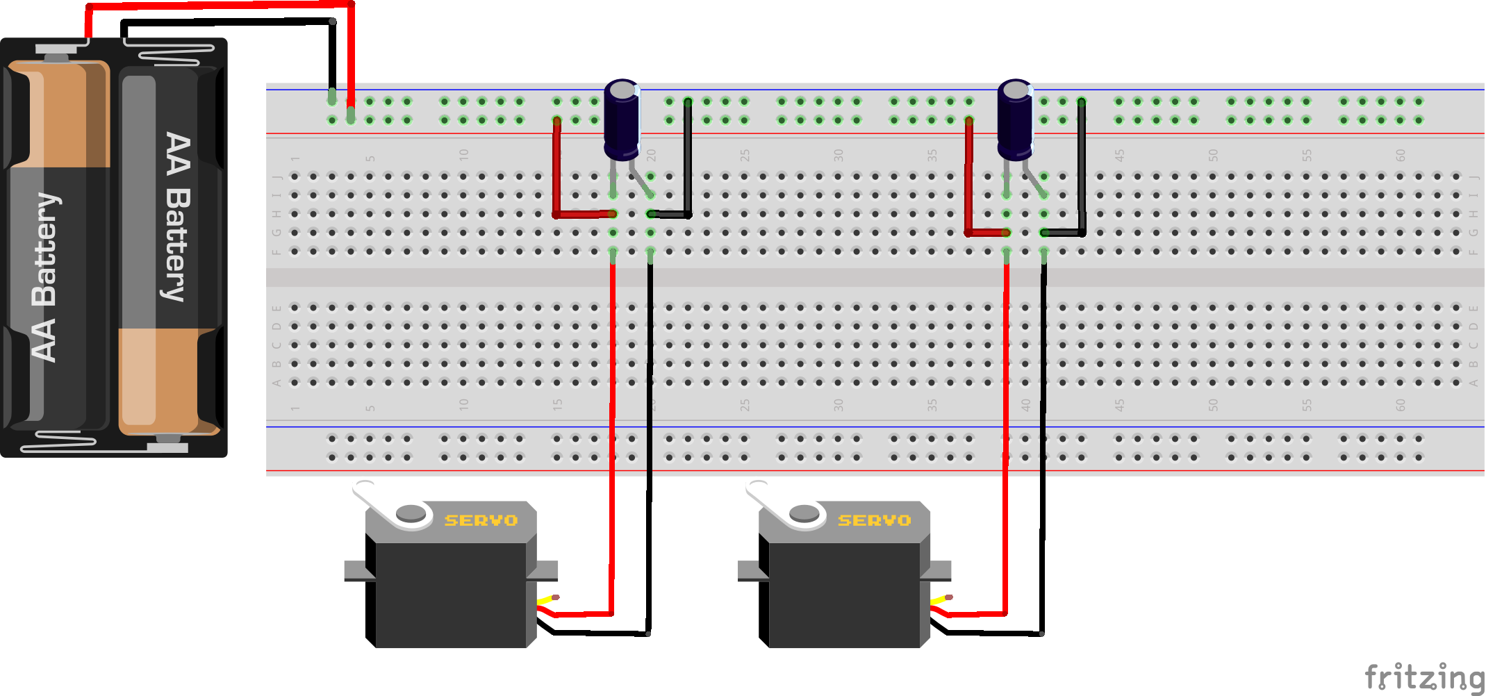
Here an example of two capacitors located close two servos:
Here my question: the capacitor should be placed between VCC and the servo (as C1, in the order VCC-C1-Servo ), or is it the same if the capacitor is placed immediately after the servo (as C2, in the order VCC-Servo-C2)?
It is clear to me that capacitors must be placed as close as possible to the servos.
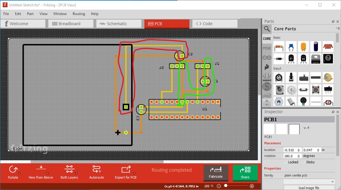
For the servos either way should be fine. The thing you want to take care with isn’t shown though. The Idea of the bypass caps is to avoid resistive drop in the ground line affecting logic levels. To help with that you should put the servo grounds as close together as possible and feed them with a trace directly to the battery (this is the high current path cirlced in red here) then connect the power to the microprocessor from the servo grounds so there is no voltage drop due to high currents between the microprocessor ground and the servo grounds.
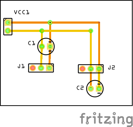
Another bypass cap goes between microprocessor ground and power to keep the microprocessor supply stable. Here is the sketch that created the above picture: