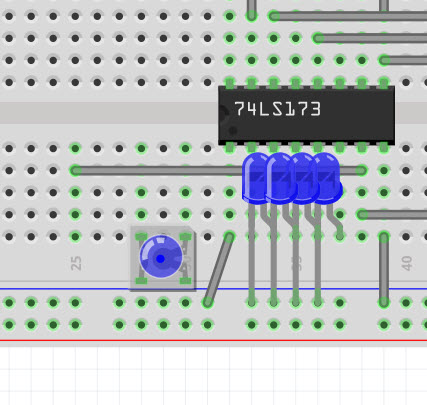
When I select an LED, then right click and choose Raise and Lower -> Bring to Front, the wires on the breadboard still appear over top of the LEDs. I’ve also tried lowering the wires to the Back, and that doesn’t help. Can anyone suggest something else I can try? Note: I don’t want to rotate them 180 degrees.
Yah, I couldn’t get them to move either on a test file. I have used this process before and I’m sure it worked as advertised. It seems straight forward, you would think.
Maybe Vanepp or one of the others will have an answer for you.
I had that problem before, but I can’t remember what I did. Maybe close it and reopen it.
You can upload the .fzz here with the 7th button and I can have a look at it.
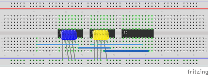
A work around in case there isn’t a solution, would be to move the leds up 3 holes so the body of the led overlaps the IC and the wires are then below the body. That then obstructs the pins of the ICs, which may or may not be acceptable. I think (but don’t know for sure) that wires may always be on top to make connections visible. If obstructing the pins isn’t acceptable then I’d probably edit the led part and reduce the size of the led body far enough to suit. Here is what I mean with generic ics and only some of the wires present:
Peter
On an unrelated note, you likely want current limiting resistors (likely about 220 ohms) in series with the leds. As long as you use 74ls173s you may get away with it as is as there is a 100 ohm resistor to Vcc on the high side, although that may cause excessive current draw on the supply lines for the chip especially with all outputs high.
Peter
I think VAN is right about wires in BB view always being in front, i.e. so that you can always see the connector hole.
I think I vaguely remember a part on the other side of the PCB in PCB view not coming to the front, so it was something different.
Thanks for the replies everyone. I wasn’t able to reply for about the last 30 hours because my account was under review for some reason. Anyway, I found a way to bring the LEDs to the front, but it’s not reliable, and it doesn’t seem to last once the program is closed and reopened. But for what I’m doing, that is sort of ok as I really just need the screenshot. Though I really wish it would last when I closed the program because I often have to go back to these files, make a change, and take a new screenshot.
Anyway, what I found was that if I select all the LEDs by shift clicking them one at a time, and then I delete them, and then press CTRL+Z to undo, it will place the LEDs on top of the wires. But … #1. it doesn’t always work. I haven’t yet figured out what conditions trigger it. #2. When it does work, it doesn’t always put all the LEDs on top. Sometimes I’ll see that there are still 1 or 2 that appear under a wire.
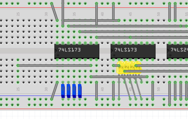
But when it does work… I get this…
Finally, I’ll include this link to a PDF I’m working on (1 of many) that shows what I’m doing. As you can see in the PDF, all of this breadboard stuff is being done in an iterative way as to explain a process.
https://drive.google.com/open?id=0B-6ynjm4RtfudnNrRTFOWGNOUVE
Holy carp, that was a bit of work.
I couldn’t get the trick to work.
If you’re interested, I remember VAN making a LED that is smaller because it’s more a top view, and because it’s smaller it might fit on the space between the power rail and the BB pins.
It’s pretty random. I can usually get it between some combination of CTRL+SHIFT+[ with some parts and CTRL+SHIFT+] with others. I think part of it may have to do with putting the breadboard itself in the very back and then locking it. I know I’ve done that, but I don’t know if that was a key to making it work or not.
Here’s a quick video of me doing the trick. http://www.youtube.com/watch?v=iVCV9WowBcs
The first time before recording the video, what I did was to select each LED and then DELETE followed by CTRL+Z. That didn’t work. So I just tried DELETE and CTRL+Z again. Still didn’t work. Then, with all the LEDs select, I did CTRL+SHIFT+], then DELETE, then CTRL+Z. And that worked.
But when I recorded this video, that pattern didn’t work, but some other pattern did. So there is no absolute sequence that I can figure out that works every time.
Which LED? I know I can reduce the size of the LED to 3mm, and I’ve seen some other LED that appears flat … and that would be great … but the one I’m thinking of takes up a 3x3 area (which is too big), and it isn’t the right size for going between a row and a power rail.

Talk about inconsistent, no luck here.
FZ has a redraw bug where if you get odd-ball stuff it can only be corrected with a close and open, so it’s lucky that you got it in between that.
I think the LED - could have been a transistor - was somewhere between top and std side view, but my memory isn’t that good. It doesn’t seem to be in parts submit so it might have been in help, but either way I suppose someone could make a 2 pin LED out of that 4 pin one.
EDIT
I had a copy afterall
LED_Red-5mm_top-view.fzpz (6.2 KB)
Looks like that only works for the red version though, when I change to blue it goes back to the normal size one. I originally suggested editing the part so I 'll have a look at it (a quick try ran in to problems as the configuration is odd, the leg connectors are set as a group which I didn’t think was possible, and doesn’t work if I make changes). I expect I need to modify the fpz file in the end to match the ones in core so all the core magic will work on the new part.
Peter
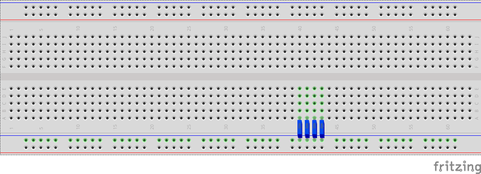
While this one isn’t quite finished yet (clicking on the color or case in inspector still breaks it) I suspect it will do what you want:
Here is the current part that created this (it is called _3 because I have another that fits beteen two .1 pins where this one needs .3 to be useful where it currently is.) I’ll have a bash at fixing the meta data as SteelGoose suggested in another thread so that it ignores changes to inspector and hopefully won’t change to the round version and won’t change back. Unfortunatly at present there will have to be one for each color, but that isn’t too difficult. I expect a code change would be needed to make inspector treat it like the round leds.
Square_3_blue_led.fzpz (6.3 KB)
Peter
Sweet! That is the perfect LED for what I’m doing. Also, I use rectangular LEDs in my breadboard projects because they are easier to fit side-by-side on a breadboard. So not only is it better looking in Fritzing, it’s also a more accurate view of the actual project.
Here is the same thing in yellow (yell if you need other colors they are easy) since I don’t expect you care right now that inspector is broken and this should get you going  .
.
LED_square_yellow.fzpz (7.1 KB)
Peter
Thanks I appreciate it. Red (635nm) and Green (555nm) would be the only other colors I’m using at the moment.


