Hi all, and thanks for this wonderful area to discuss Fritzing.
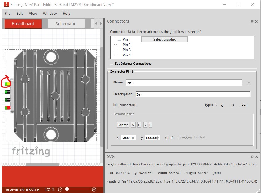
My problem is that I cannot get the crosshairs on a graphic after I load an image to view. I open the connectors window, select the pin, click Select Graphic, and from there I get no more response from the program. No checkmark, no crosshairs. This happened yesterday, but I paid for the latest version and it worked wonderfully. I tried to recreate the parts I had successes with, all to no avail. I recreated the image in Inkscape making sure the graphic for the pins were top level, I saved it properly, and tried again.
I restarted the computer a number of times, and I still have the same issues.
I tried the same graphic onto another computer and it worked just fine.
Best bet is to upload both the .fzpz file of the part and the svg you are trying to load in to the part (upload is 7th icon from the left in the reply tool bar) and one of us will have a look at it and see if we can see the problem. I tend to not use parts editor because I usually have this same problem (not being able to associate pins) and therefore tend to edit the files directly without parts editor, but others don’t have this problem.
To my amazement it worked for me. I made a .fzpz file out of your svg file and fzp file (needed to modify the .fzp svg file names to match the .fzpz format though.) and loaded it in to Fritzing and started parts editor on it.
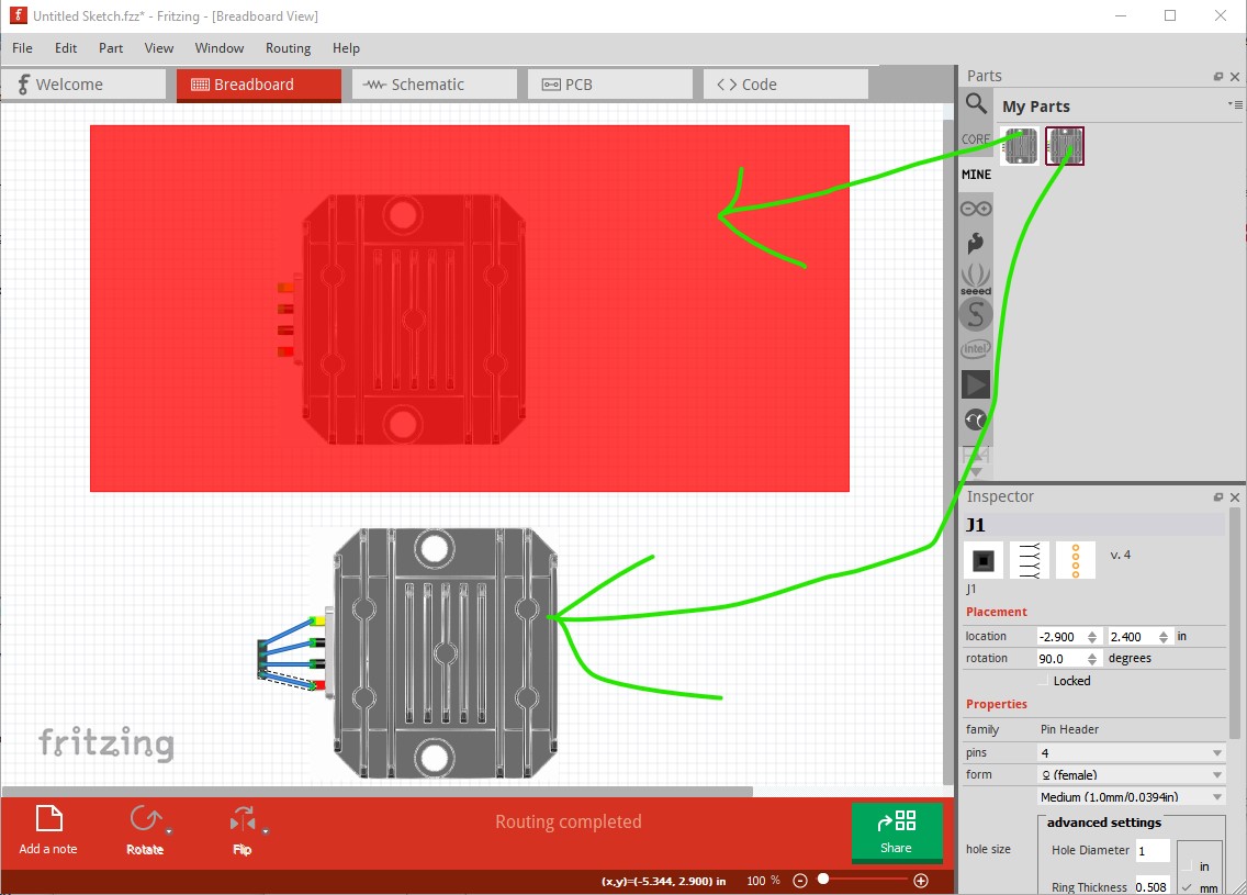
clicked on select graphic then clicked on the green square and it made that pin1. Repeated for the other 3 pins and saved then exported the file, then dragged the new part in to the sketch (the red square on the top one indicates no connectors on the original file)
there is a problem with your svg though, the pins are not aligned on .1in boundaries as we see in the above image. The wires between the connectors (which are on .1in boundaries) don’t align with the pins on your svg. Here are the .fzpz files for the two parts:
this is the original svg (no connectors defined.) If you unzip the .fzpz file you will get
‘part.Drock Buck cant select graphic for pins_1299808866b534ebfe8512f9fbcb7ca7_2.fzp’
‘svg.breadboard.Drock Buck cant select graphic for pins_1299808866b534ebfe8512f9fbcb7ca7_2_breadboard.svg’
which is what a .fzp and svg file look like in a .fzpz file. The same two files will appear from test.fzpz, but the svg will have connectors defined. I’m using Fritzing 0.9.9 on Win 10 to test this but it should be the same for any version I think.
and this is the file from parts editor (exported as a .fzpz file by right clicking on the left part in the mine parts bin and selecting export part and named it test.fzpz)
Peter, thank you for the detailed info, I am going to share this with my team, itll be a great addition to our learning. I am not terribly concerned with the 0.1 spacing, as the part represents its true spacing, and there happen to be many bends in the wire before it gets to another custom part.
I too, was able to finish the part on another computer I have Fritzing loaded on (I now have 3 available to me) so that was the workaround, in this case.
I am still curious why the program wont see or recognize the pins on the initial computer I tried.
Thank you as well for showing how to save as a .fzpz, Ill be able to do that for next time I need to share.