I am very new with Fritzing.I want to make pcb of a guitar preamp with a schematics.But i cannot make the PCB.
Please any one help me to make the pcb with a 3"x1" board.Fritzing file is attached.
STG_Pre.fzz (17.9 KB)
I guess you want to organise the placement of parts in PCB.
Spread the parts out and put ICs in the middle, because it connects on all sides, and click on a pad and all the connected pads will turn yellow. Best to keep connected stuff together. You put inputs and outputs on the outside, either together or opposite sides. Things in rows, groups, etc look more professional.
There is no perfect way to do it, so it just shuffling parts and manually routing.
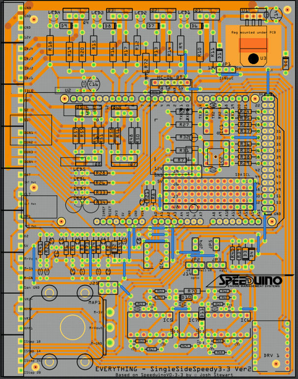
This one took a week.
I cannot organise the components on a 3"x1" size board.Please help me.
Why not? They will fit for me. It is highly likely this isn’t correct since I just changed the pcb size in inspector to 25.4mm by 76.2mm (1*3 in) then dragged parts around until they all fit. In actual practice you need to arrange the parts in a sensible manner that both layout and routing work. This is a lot of work in a confined space, but not rocket science. If I was really doing this I would start with a copy of the schematic (probably on paper) and move the parts to an appropriate place (for instance with C1 and C2 on the left side of the board on the top and C4 R4 R5 C5 under them and proceed right. You may then need to move things as you route traces and find that routing won’t work. Try it and if you can’t make something work post it and we will make suggestions.
STG_Pre_mod.fzz (17.7 KB)
(edit:) Before worrying about the board however your schematic needs some things. A pair of 2 pin connectors for input and output (signal and ground) the current input / output on schematic are schematic only and don’t appear on the pcb and you need to be able to get the signal in and out from the pcb. The 2 pin connectors will create pads that you can solder wires to. As well you need to determine where the 9V (battery?) and 5V (?) are coming from again with a connector that will result in pads on the pcb to connect to (and possibly a regulator if the 5v is obtained from the 9V supply). Then you can start laying out the pcb.
Peter