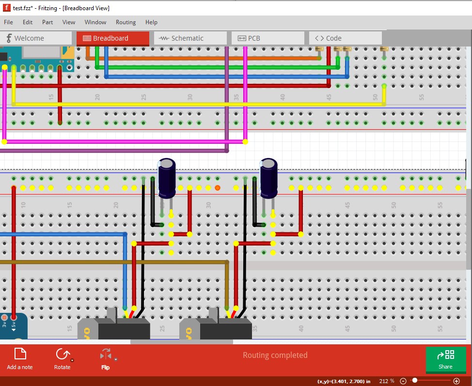
This is the first creation I am wanting to build. I have been doing research for a while but not sure if this would work… blowup… short everything. Any and input much help is appreciated, I am not done with the PCB or Schematic yet. I am using a 11.1 v 2200mAh LiPo battery to power this. Test.fzz (105.1 KB)
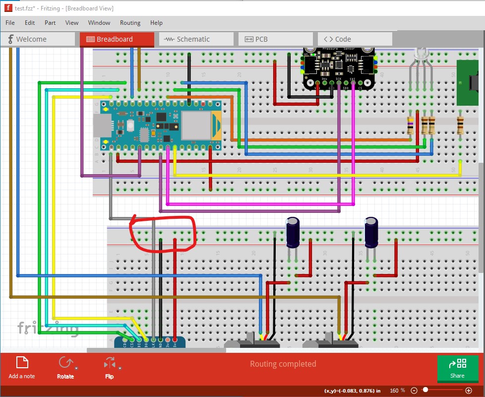
Welcome aboard! You have many problems, it will not work as it stands. Mostly I have questions as I’m not sure what some of the stuff is intended to do. First, you are missing a ground wire. There is no wire between the battery ground and the rest of the grounds below it so the bottom two breadboards are not grounded.
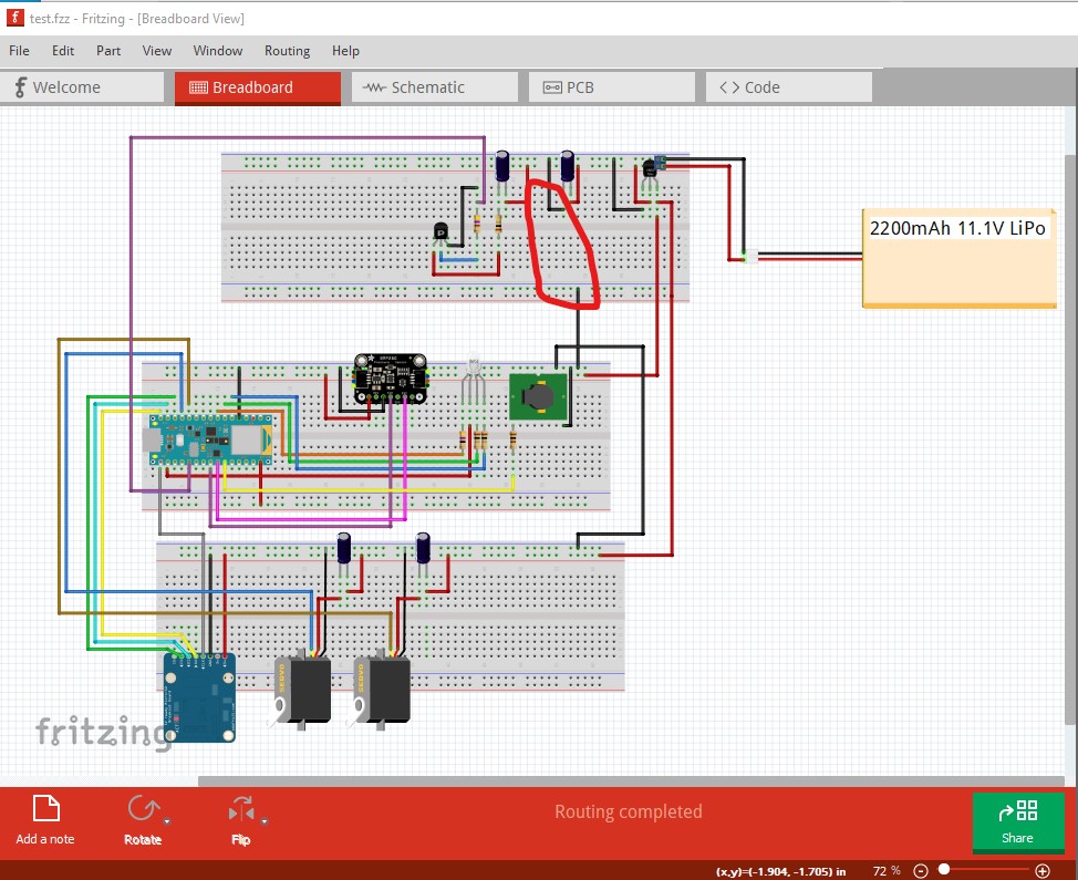
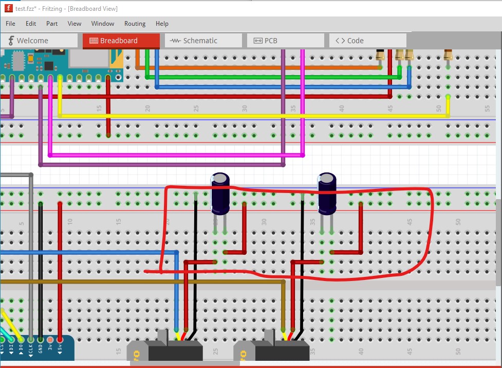
there needs to be a wire between the two circled wires to connect ground to the bottom two breadboards. A useful Fritzing trickL: if you left mouse click on a connection, all connected wires will light yellow. Here I did 5V power which is correct:
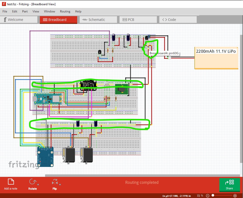
Doing the same on the ground indicates the problem:
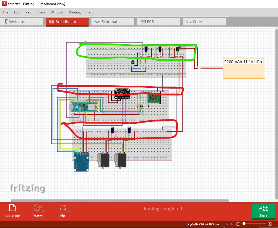
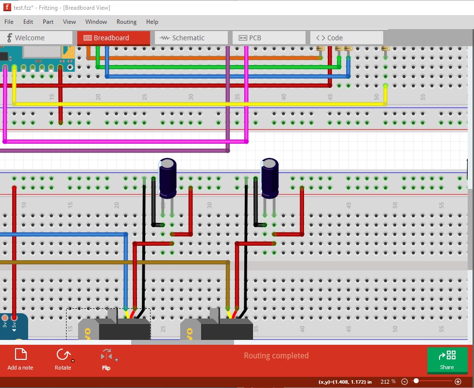
the bottom two grounds don’t light yellow because they aren’t connected. As well there is a misplaced ground wire (it goes to 5V instead of ground!)
The black wire should be up one position to connect to ground. The servo connections are incorrect. The capacitors should connect across the power and ground lines to the servo not in series with power (that will make the servo not work!) Instead of this
do this
Then the 5V connection to the left servo isn’t connected.
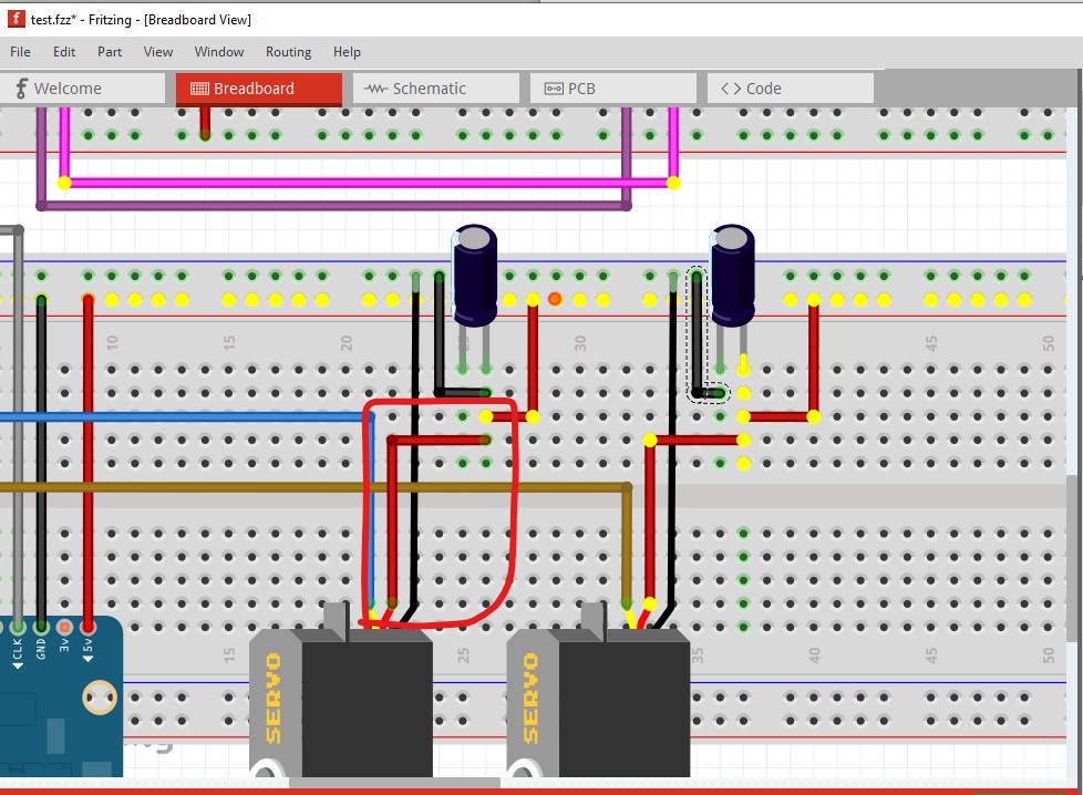
note the red wire and the servo power pin are not lit yellow. move the wire slightly with the mouse to connect it.
so the servo power connection lights yellow. Now some suggestions for changes and some questions. The 7805 regulator is a poor idea in a battery powered system. They are only about 20 to 30% efficient. Since you seem to be using a lot of adafruit, this would be a better choice. It will accept the 11.4V battery input and provide 5V at up 1.2A at 80 efficiency. There are many similar (some with Fritizng parts) available on Ebay et. al. as well that would also work.
It isn’t clear to me what the fet is for. It currently doesn’t do anything because it isn’t connected to anything (missing a ground connection on the bottom of R5?) but even then it doesn’t do anything.
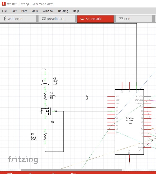
as nothing connects to the end of the capacitor. Also the resistor values are likely too low. Next I wonder why the BMP280 is there. There is already a pressure sensor included in the cpu why not use that? That would save both space and power. You also need to check how much current the servos draw at 5V. With the suggested regulator it needs to be less than 1A.
edit:
A point I forgot above. You need to power the SD card module from 3.3V (probably from the CPU) not 5V. The cpu pins are not 5V tolerant and the SD card will apparently run from 3.3V but has level translators which will output 5v signals if powered at 5V. As well the cpu pins can only supply 15ma per pin so the resistors driving the LEDs need to be higher value to limit the current draw to less than 15ma each. You also need to connect the battery (unless the usb connection will always be active) to the Vin pin on the CPU module. It will run fine on 12V connected to that pin.
Peter
1 Like
Oh my goodness thank you for all this information I will take a look and get back to you!
No hurry, I’m usually here. A last piece of advise: do all of breadboard first (without doing schematic or pcb.) There is a bug in Fritzing where making changes in more than on view corrupts the routing database and usually requires starting the sketch again from scratch which can be very frustrating. We will probably need to go through multiple iterations to get this right as well.
Peter
Peter,
Again thank you for all the input It took me longer than expected to review this. I forgot to mention but this is for a model rocket flight computer. The mosfet was supposed to ignite the rocket motor (I saw this online). I need a way to ignite these from the Ardunio [Model Rocket Starter] (StarTech™ Model Rocket Starters (Estes) )
To start I removed the BMP280 and decided to use the one build into the Ardunio,
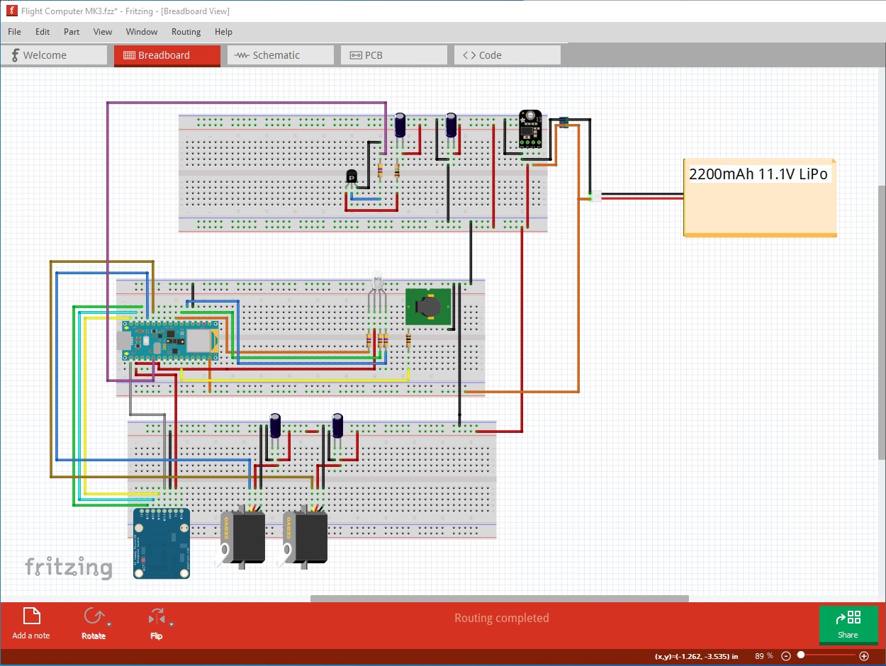
Next, I decided to add the MPM3610 Buck converter you recommended although I am not entirely sure how to connect it. I upped the resistor values to 470ohm for the LED. I believe I fixed the Servo and capacitor wiring. I changed the SD card to 3v power on the Arduino. Am I able to power the buzzer and SD card from the 3v Arduino? Any more help is appreciated!
Flight Computer MK3.fzz (92.6 KB)
I know someone that worked on a model rocket launch system. One of the legal/safety requirements is to have a physical interlock that prevents ignition until the interlock is removed. To prevent accidental launches when people are setting up. That interlock is typically a way to physically disconnect the power from the ignition system that is very visible. So a glance (from a distance) can tell that it is locked out.
OK, here is a more complete copy of your sketch. The igniter is still not correct though, it won’t do anything as it stands.
Flight Computer MK3-completed.fzz (95.0 KB)
Here I connected the battery to where it needs to go for the 5V regulator and to power the CPU. As noted the firing circuit doesn’t work (and I don’t think it will, but I know nothing about rocket igniters!) From reading this web page
on the igniter it appears to wants 12V at around 8A to fire. A small fet isn’t going to pass that much current and a 2200ma/hr LIPO battery likely won’t provide that much current (it may, if not protected, in fact catch fire or explode!) It may be intending to get the current from the capacitor, in which case it likely needs a charging current limiter to protect the LIPO battery. As @microMerlin pointed out, the instructions indicate the need for a physical key to interrupt the firing circuit (and I can see why!) You likely need to consult someone in the model rocket community on how to create a safe and working firing circuit for this project, I don’t know enough to give you safe advise (except be very careful and safety conscious as a mistake may be deadly to yourself and others!)
Peter
Peter thank you again for helping with my project, you have gotten me one step closer to completion! I will consult someone in the model community about what precise tools I will need to get this thing going again. Thank you for all the time you have spent when I finish I will upload the project to this page!
OK, a couple of final suggestions: here is a Fritzing part for the igniter
rocket-ignitor.fzpz (4.5 KB)
because you will probably need a part to represent it. That said, the igniter is intended to stay on the ground when the rocket launches. I think the intent here is to trigger the igniter from inside the rocket using the internal battery (although I may be wrong!) To do that you may want to look at pogo pins like this
a pogo pin is a spring loaded pin that compresses to make contact (typical use is test jigs, but it should work in this application too.) If two of these stick out of the bottom of the rocket, they can connect to pads that connect to the igniter. When the igniter fires, the rocket takes off and the pogo pin disconnects without snagging the rocket as another connector may do (and potentially send the rocket off course which could be dangerous.) The best bet as I said is to consult someone in the model rocket community that has made a rocket like this. The other thing to consider is that the parts on your pcb board are going to be stressed by G force (probably several Gs) on takeoff. That means that you need to take care that the components are solidly mounted to the pcb board so they don’t break of and/or malfunction during takeoff. In particular the SD card needs to be facing up on the axis of flight so the G force causes it to push down in to the SD card socket (don’t mount it sideways as it may twist and become disconnected!) Again consult with someone who has successfully made one of these work (preferably more than once  ) to find out what works best! Good luck!
Peter
The launch system I am familiar with is totally ground based. The rocket had its one telemetry system, but it had zero interaction with the launch system. The launch control system is generic, in that it can be used for multiple different rockets. Over time, at a single “launch pad”. With or without a “smart” rocket.
It appears to me (because the micro has a Cell interface and an igniter circuit which currently doesn’t work) that the intent here is to be able to trigger the launch from the rocket itself via a cell call. That being the case (which may or may not be correct!) there needs to be a way to trigger the igniter (which does seem to need to be external) from the on board battery/micro combination. I would think it has safety issues, but perhaps there is a way around them.
Peter
update: we decided to get rid of the MOSFET and stick with a ground-based manual launch system for now. eventually, we want the rocket to be able to do everything by itself or have a ground-based computer system of some sort.
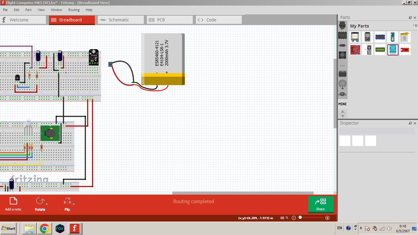
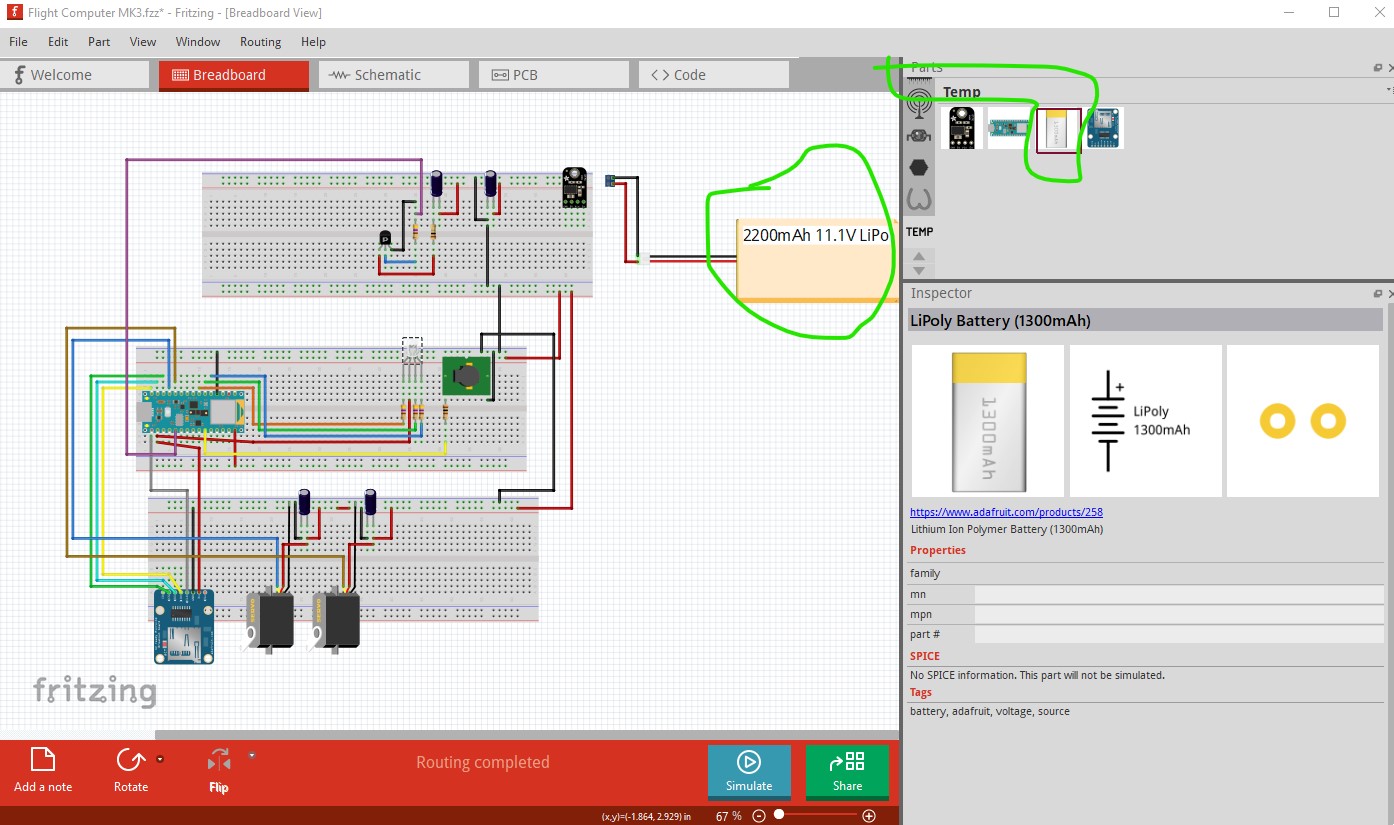
Can anyone please tell me where can I find the 11.1 v 2200mAh LiPo battery shown in this project, In can,t Find it anywhere, please?
If you download the Flight Computer MK3.fzz file above it is in the temp parts bin. It looks to be an adafruit part (probably 3.7v) with a text overlay in breadboard.
edit
forgot the jpg
Peter