Ficha 2.fzz (7.4 KB)
I allready have done some part on breadboard, but i can’t to do the rest, if someone could help, i would appreciate.
Ficha 2.fzz (7.4 KB)
I allready have done some part on breadboard, but i can’t to do the rest, if someone could help, i would appreciate.
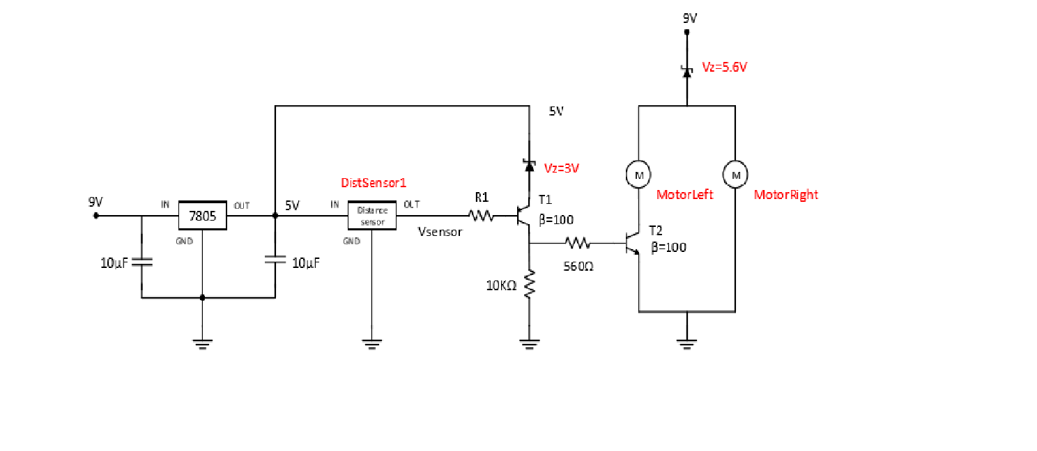
This is an odd (and perhaps not functional) schematic. As it stands the right motor will always run, and only the left motor will change in response to the distance sensor. I’d probably start by verifying that the schematic does what you want to do (because it doesn’t look like it at present.) That said, to complete the sketch you need to find the appropriate parts in the parts bin, 2 zener diodes (search for zener diode), an npn and pnp transistor (in the core parts menu on the first line) and two motors (search for dc motor in parts search) and drag all of them in to your sketch. You should probably start in breadboard (deleting all the wires in schematic for now or at least the one on the output of the distance sensor) then connect the parts up according to the schematic above on the breadboard. When the breadboard is completely wired then change to schematic view and click on the dotted lines (the rats nest lines that indicate the connections in breadboard view) and route the resulting wires by dragging them. If you make connections in more than one view (or make connections not indicated by a rats nest line) you may corrupt the routing database and need to start the entire sketch again to clear it. As well, as in your first sketch. the connections in schematic are not correct.
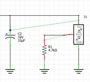
The red (rather than green) connections on the VCC pin of the distance sensor and both sides of resistor R1 along with the dotted rats nest lines indicate you don’t have proper connections there.
Peter
Ficha 2.1.fzz (9.1 KB)
Can you see if this is right? i’m pretty sure it is wrong.
Thank you
Indeed it is not correct. The vertical strips on the breadboard (all 5 in a column) all connect together. The parts need to be connected so that each pin is on a separate strip. In case you are going to actually build this I added a back emf diode across the output transistor. Without it back emf from the motor is likely to damage the transistor. I also deleted all traces in schematic to start with so only breadboard is connected.
Ficha 2.1-fixed.fzz (9.3 KB)
Peter