Hi there,
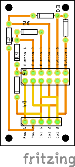
in order to make the wiring for a button easier, I had the idea to create a small PCB for that.
So just connect a buttons and connect the sx1509 to it.
Now my question is, how can I improve the wiring? Because of the diodes, I had to move the traces a lot and I don’t know, if they are pointing into the correct direction.
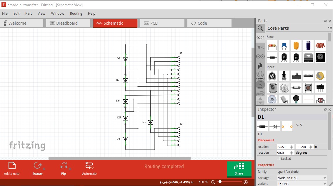
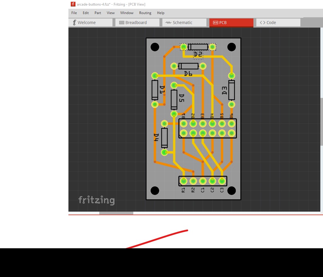
while this doesn’t tell me much (as the keys on the connectors are not shown) it should match how you think the connections are to be made. Because it was made from pcb it will reflect the connections in pcb. It is often difficult to tell if pcb is correct or not. Next I checked each connection in pcb by right clicking on a connector like this:
I right clicked on the pin pointed to by the green arrow. That causes all pins connected to it to light yellow. Doing that for all the pins indicates they are all connected to each other as they should be. Note the diodes are all on the bottom of the board (which may be as intended!) while the two connectors are on the top. This is not wrong just unusual. The silkscreen for the diodes will be on the bottom of the board although the diodes can be mounted on either side as long as the polarity is observed. If you didn’t want this change the pull down menu on the lower right from bottom to top to move the diodes to the top of the board. Below is your sketch with schematic routed.
Hi,
thank you for your detailed answer and help.
The buttons are six arcade buttons, which have do have two pins. So on J1 there is one button per column. Do you need to know more? I wanted to have it flexible, thats why each button has a cable with a cable lug on the button side and a male pin header on the other side.
The connectors are supposed to be female pin headers, so I can just plug them in.
The J2 connector is a female pin header too, so I can just take a jumper cable and plug it in there and the sx1509 port expander.
I moved the diodes to the top of the PCB and moved everthing a bit around, so it doesn’t take up so much space.
Are all diodes pointing into the correct direction? Do I need more for a matrix or is this fine?
When the PCB is fine now, I would let manufactor it. I was able to find some “1n4148” diodes, but finding 5-pin female header and a 12-pin 2-row pin header is quite hard .
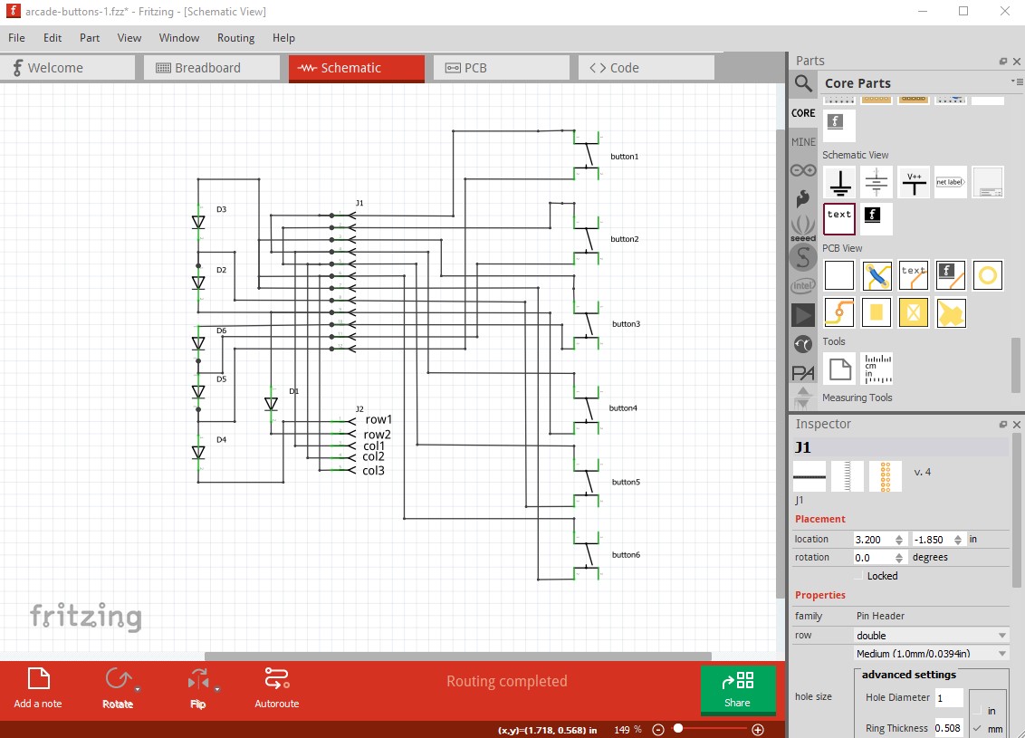
Yes, if I had known you were looking for headers I would have pointed you at the generic header part (which I see you found.) Here I have added the switches connected as I think you intend: button1 on pins 1 and 12 of J1 button2 on pin2 2 and 11, etc. to schematic. That indicates the diodes are not correct as connected:
pcb here has all traces removed so will need to be rerouted. In general due to a Fritzing bug we haven’t found yet, it is safest to complete one view (breadboard schematic or pcb) and then use the rats nest lines to route traces in the other 2 views.
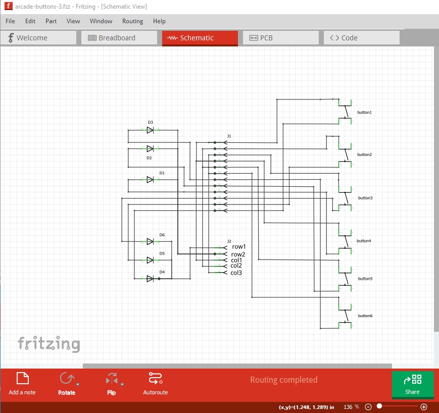
Okay, I finally finished the routing… arcade-buttons-3.fzz (21.5 KB)
Is this version fine? I’m asking, because I want to submit it to AISLER.
What I meant with finding the pin header is finding the correct part number, so AISLER can add them to the PCB already, the diodes are fine.
In addition before ordering boards I would wire the circuit on a breadboard and make sure it does what you want. While it looks correct it may in fact not be correct, a test of the actual circuit is the best way to verify that.
While I rarely make boards and have not used AISLER some one else did and the board came with the parts but not assembled so you may need to check with AISLER to see what your options (and costs!) are for assembly.
From other sources, they may require a ‘pick and place’ file, which Fritzing does not generated. That could be non-trivial project. I think it would need 3D information about the parts to be placed. A lot more information than currently available in existing Fritzing parts.