Hey everyone!
I wanted to share with the community a part I developed for my thesis: a complete component for the BU01 module, based on the Decawave/Qorvo DW1000 transceiver, for Ultra-Wideband (UWB) positioning and distance measurement.
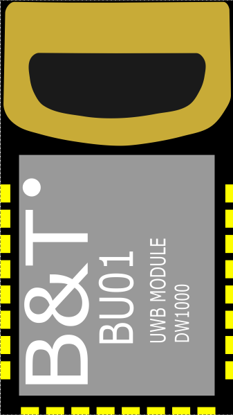
I couldn’t find a ready-made part in the official library or in Fritzing Parts, so I ended up modeling all three views from scratch — including the breadboard illustration, built up layer by layer in a drawing program (the gold connector, the castellated pads, the case gradient), which was the most time-consuming part but the one I’m happiest with. I’m sharing it in case it’s useful to anyone else working on localization/RTLS projects.
Module Description
BU01 (DW1000) is a compact Ultra-Wideband wireless module based on the Decawave DW1000 transceiver. It enables high-precision real-time positioning, distance measurement, and low-power wireless communication via an SPI interface.
Specifications:
| PROPERTY | VALUE |
|---|---|
| Communication | UWB |
| Frequency | 3.5–6.5 GHz |
| Interface | SPI |
| Chip Manufacturer | Decawave / Qorvo |
| Module Type | UWB positioning module |
| Protocol | IEEE 802.15.4a |
| Voltage | 3.3 V |
| Family | RF Module |
| Variant | BU01 DW1000 |
Connectors (24 pins)
The component includes all 24 pins correctly mapped and labeled across all three views:
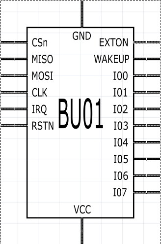
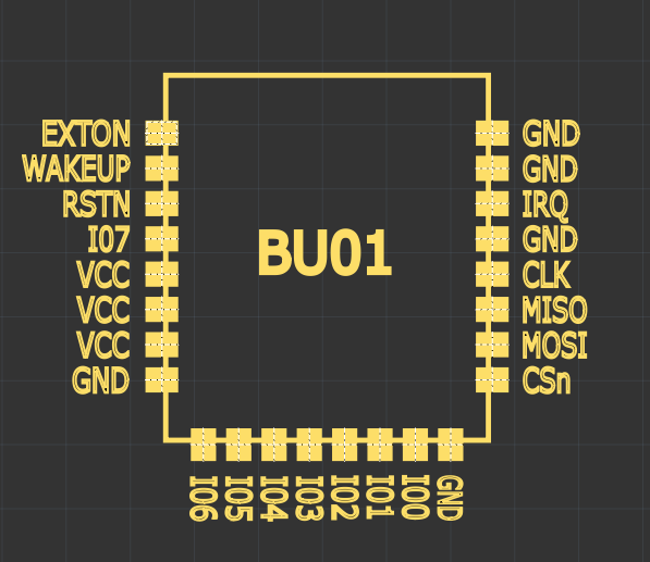
EXTON, WAKEUP, RSTN, IO0–IO7, VCC (x3), GND (x3), IRQ, CLK, MISO, MOSI, CSn
Included Views
Breadboard: illustration of the module with castellated pads on both sides, faithful to the real physical form.
Schematic: rectangular symbol with pins grouped logically (control/SPI on the left, IOs and power on the right) for easier circuit reading.
PCB: SMD footprint with castellated pads ready for routing, with each pin label visible on the silkscreen layer.
Download
.fzpzfile:
BU01 (DW1000) UWB Module.fzpz (43.2 KB)
License / Attribution
The design of this component (footprint, schematic, and illustration) is my own original work. The DW1000 is a product of Decawave/Qorvo; this file is not affiliated with or endorsed by the manufacturer — it is simply a representation of the module for use in PCB design.
I’m sharing it under [CC BY-SA 4.0] — feel free to use it in your projects.
Feedback
This component ended up being part of my thesis work, so I put a lot of care into making it complete and polished — all 3 views, internal connectors assigned, metadata, and a custom illustration. That said, if you spot any mislabeled pins, spacing issues in the footprint, or anything else that could be improved, I’d love to hear your suggestions.
Cheers!