I’m new to Fritzing but I’ve used a lot of professional CADs in my career, none of them had breadboard or stripboard capabilities which are very useful for a retiree so I did my choice.
I have two questions :
1-is there is a particular syntax for searching the component list only in the title.
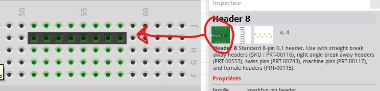
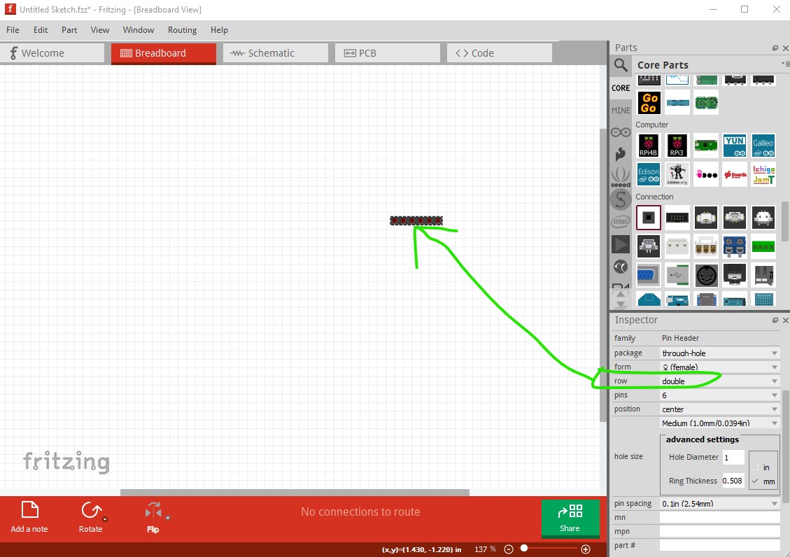
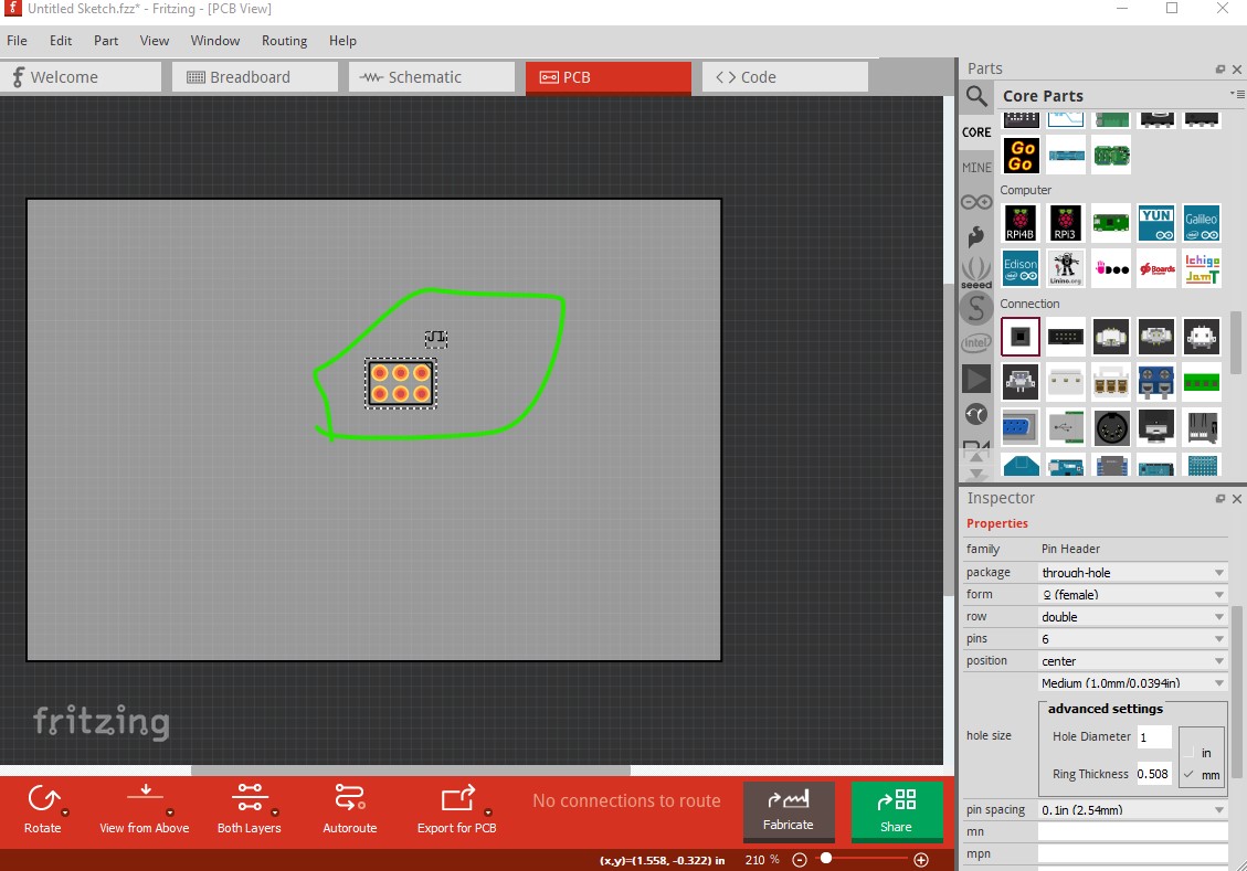
2-if I understand well the leftmost image on the inspector is the icon for the breadboard but what about the following image , I don’t get the same thing. What did I miss?
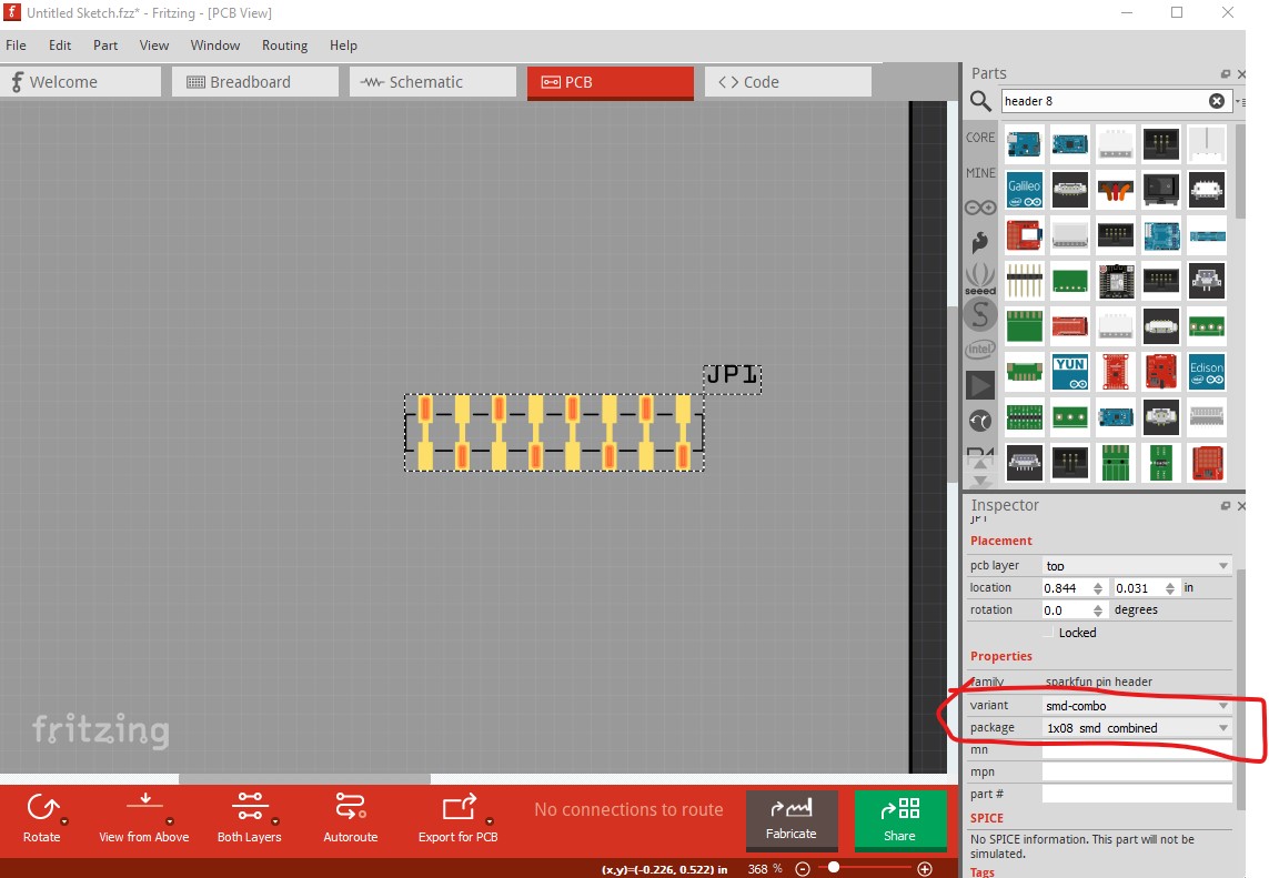
Welcome aboard! You have likely selected a THT variant in Inspector (the lower right window) the version you want is SMD (selector circled in red here)
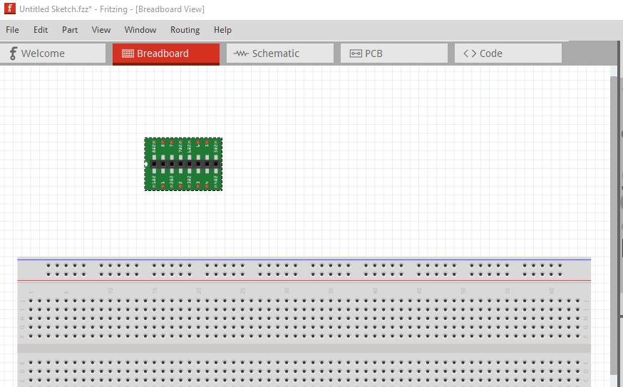
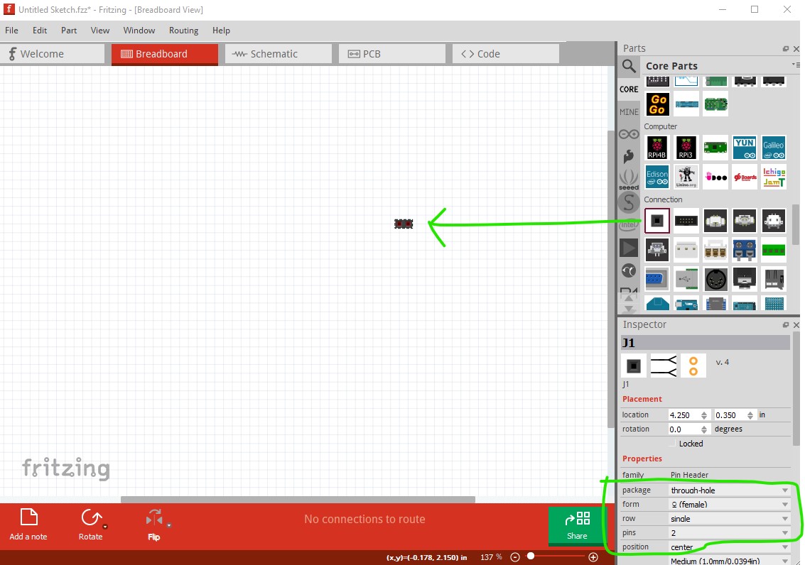
you can use Inspector to change number of pins, sex (male or female) and various other attributes. However the change can only be made to a connector in a sketch (it won’t work in the parts bin.) Also dual row doesn’t display correctly in breadboard (it comes up as single row)