As a variation of that, I have suggested using existing parts and overlaying a image to get the desired ‘look’. Not sure if the “custom image” in the above idea was intended to be linked to the generic breadboard part. If separate, it is based on the same idea as my overlay. With an enhanced generic part for editing pins. Probably needs selectable number of pins 2.
Related, it would be nice to be able save the configured customized parts as a new part. So the work does not need to be duplicated for another project, or figure which old project has it to copy and paste from.
Assuming I can get the python version of the parts factory working (the going has been slow as I am not all that good at python development it appears) this is one of the new parts I want to add, a part where you can specify by side of the rectangle (starting on the left, bottom right and top) with the number of pins on each side, probably the dimensions. That should be able to generate a breadboard svg (without the internal parts which would need to be added via Inkscape by copy paste from a collection of breadboard parts that I have.) The parts factory knows how to write the .fzp file and maybe the svgs (certainly schematic as it can completely create the schematic given the pin names) and hopefully the pcb layout given the physical offset of the pads and their shapes. This should considerably help make the generation of custom parts easier. As noted going has been slow (and frustrating to the point where I haven;t worked on it for months, since August or so) so I don’t know if I am going to give up or not yet. I believe I have solved the svg bounding box issue with a python add on library svgpathtools (with a modification suggested in a closed issue that still has some limitations but appears to work, stroke-widths in the paths, don’t get translated in to the final result but I have a workaround for that that seems to work for the Fritzing case where the origin of the svg is 0 0.) The latest frustration that I haven’t solved yet is that the previously working code suddenly started tossing errors that I don’t understand. At this point I have almost working code for male and female headers that will scale in both pitch and number of rows in x and y without limitation except what you can physically get. I have some problems that I need to solve around color of the headers (because you can also change colors of the headers as colored 0.1 headers are now available.) There are still 5 or 6 more parts of the current parts factory that need to be implemented but if looks like it should work if I can figure out my issues. I am essentially writing the xml for the part directly from python (rather than using lxml to try and create it, which to me, is more difficult to understand than just emitting the xml directly.) That was the suggestion of an other python package that I looked at and it makes the most sense to me. That means creating new parts requires you to understand enough to be able to write the raw xml to create a part, but I did see any way around that. I guess we will see how far I get on this project. I intend to start with a standalone python script that will create fzpz files for everything created by the current parts factory and then try and convince you to make the changes to convert the current parts factory to use it by changing the api (which I don’t know is possible!) If we can do that, then it should be possible to let users add parts factory parts for themselves which I think would be extremely useful. As noted I also hope to be able to create arbitrary pcb footprints probably from a list of offsets entered from the data sheet of a footprint. Conversion of footprints from Kicad would also be a nice addition. I have been working on this for 2 or 3 years now and am starting to get discouraged at the lack of progress but we will see how it goes I guess as it is getting at least somewhat closer if very slowly (and with extreme frustration!)
@microMerlin Yes, the image would be stored with the part, and saving such a part would then be possible.
It already is possible for the generic parts right now:
Add a dip v2
edit the pins and title
then open the parts editor
and save it as a new part
In a future version, this would be simplified by just dragging the part with custom pin labels to the my parts bin (doesn’t work yet)
@vanepp Some of this is build into the Fritizing part factories. The dip v2 (IC v2 in the generic parts in the core parts bin) also adapts the size automatically to fit the title, and wraps at whitespace.
Your factory script sounds a bit different from the image overlay approach, especially the colored headers. It is probably a different purpose, to build generic boards (pure SVG, no image overlay) Do you have one or two drafts or quick sketches how parts from this factory script are intended to look?
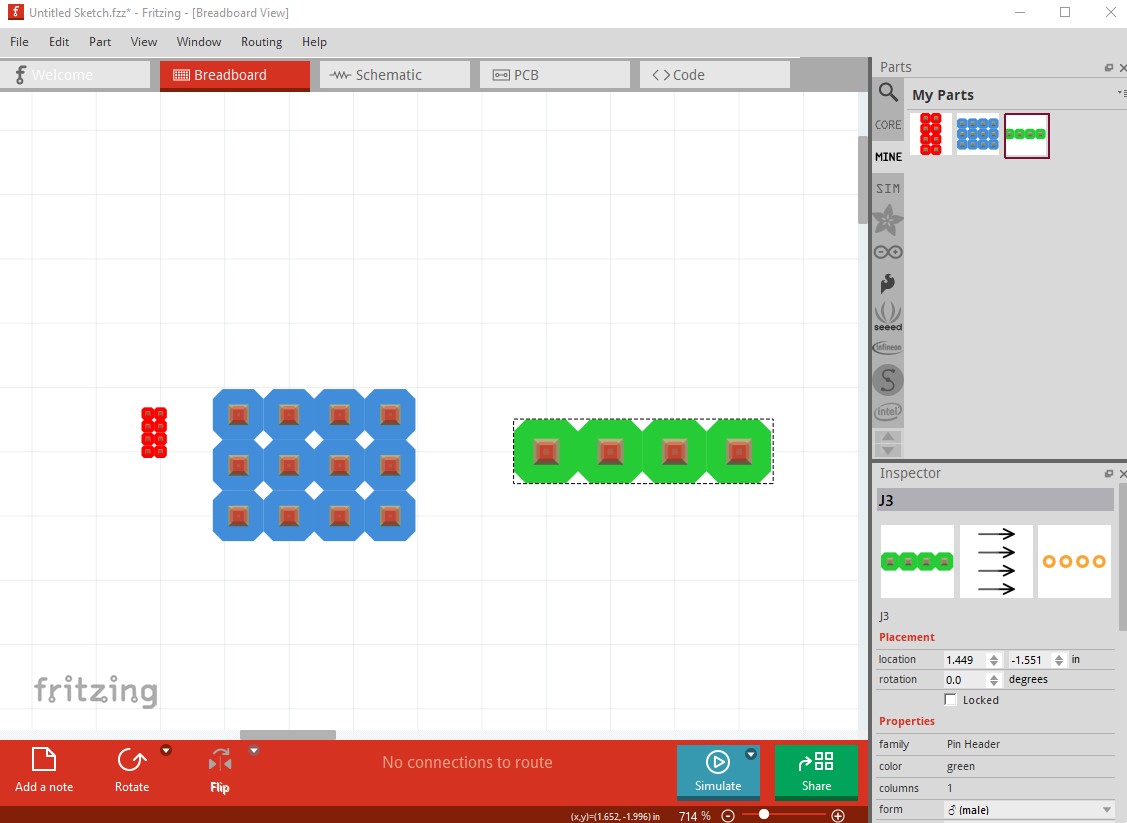
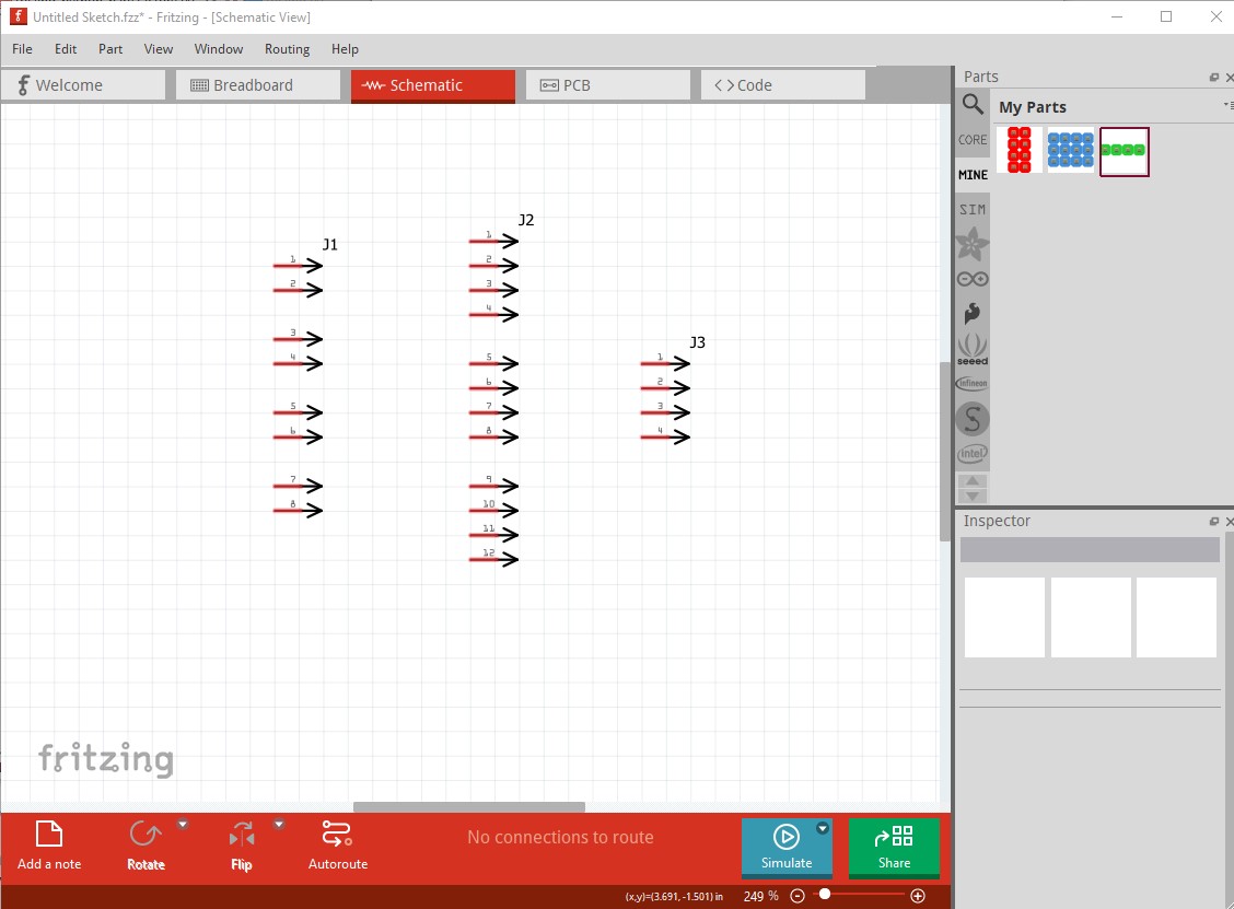
Yes, it has taken me a couple of days to fix the code up enough to work for at least male headers so here are three parts created by the script. The first is a male header (red 0.5mm pitch which is as small as I can find through hole headers commercially although I couldn’t find a data sheet!) followed by a 2mm header (in a different color) and then a 0.1in header in yet a different color. The red is 0.5mm, the blue is 2mm, and the green is 0.1in standard.
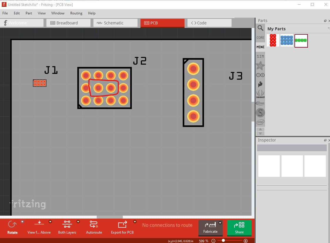
Note the 2 internal pads in pcb are not useful here as you can’t route to them (with the circle, however oblong, which allows between pad transit will work for up to 4 wide or high but probably isn’t practical after that, but the script will generate them if you can use them for something!)
Here are the three parts displayed above with the command lines that generated them: The fields run: part_type columns, rows, pitch (either human readable as here or as a number based on 0.5mm which allows any pitch you need), pcb type (SMD, THT) pad type (CIRCLE, OBLONG), row or column order for pin numbering, color (currently the same as the wire color values), Fritzing version and debug and testing file name (both for debug/testing.)
partsfactory.py MALE_HEADER 2 4 0.5mm THT_CIRCLE ROW red 1.0.5 -d DEBUG -f test
It is worth making for me as a standalone script that will produce variable pitch variable size headers with changable colors. (which was the initial plan) then I thought it may be a way to replace the pars factory with an easier to modify version if it can be integrated (if it can;t it is still worth doing as a standalone script.) Currently the reference files (at 0.5mm) are adjusted to produce pads of 0.038in at 0.1in pitch. The scaling appears to work correctly for 2mm and 1.27mm headers (although an option to increase hole size a bit may be needed.) Creating parts still requires being able to create the xml, but python is much easier (at least for me ) than c++ in QT. I expect to use it no matter to create odd parts sometimes so it is worth doing even if that ends up being its only use. As mentioned earlier I can see it may also be able to create a useful part template that would take much less work to make a full part. I guess we will see if that turns out to be true if I don’t get so frustrated that I give up, which has almost happened several times in the last number of years.
Yes (at the larger sizes like 1.27mm at least, 0.5mm is a problem) and at small (3 or 4) sizes, but an 8 x 8 leaves not enough spaces for individual traces (a bus type connection with an entire row connected together would work fine though which is why I left it in.) As well oblong pads (which aren’t implemented yet) make it better by giving more clearance to the pads.
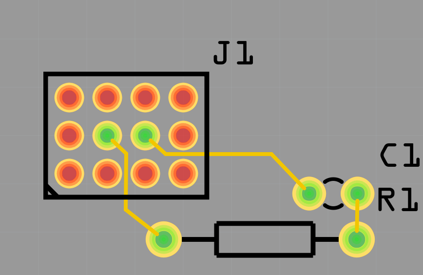
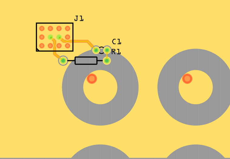
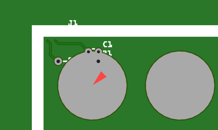
Probably a bug in the code. I’ll have a look and try and correct it. Thanks for pointing it out because I had not seen it yet! I’m thinking the next task (after finishing headers!) will be to make the projected new part template that will generate an fzp, breadboard, schematic and maybe pcb (which I expect is going to be harder.) You would still need to edit the breadboard svg (to install the components and move the connectors to the correct places) but it may make part creation at least somewhat easier. I will see how it goes. I still need to figure out what I did that broke that args class. It claims to not have attributes that are defined, but when I started making incremental changes to a working version I got to the one that works in the code that generated the parts but I don’t yet know why the original broke and I need to figure that out so I know what not to do. I take it the grep (very large pads with the offset hole in the image above are the invisible connectors? I should be able to see them in the svg I expect which should tell me where they are coming from. If not I can try a ground fill (and gerber output which I don’t think I verified in this case) either of which should identify the problem. I also probably didn’t check DRC on the test parts.
edit:
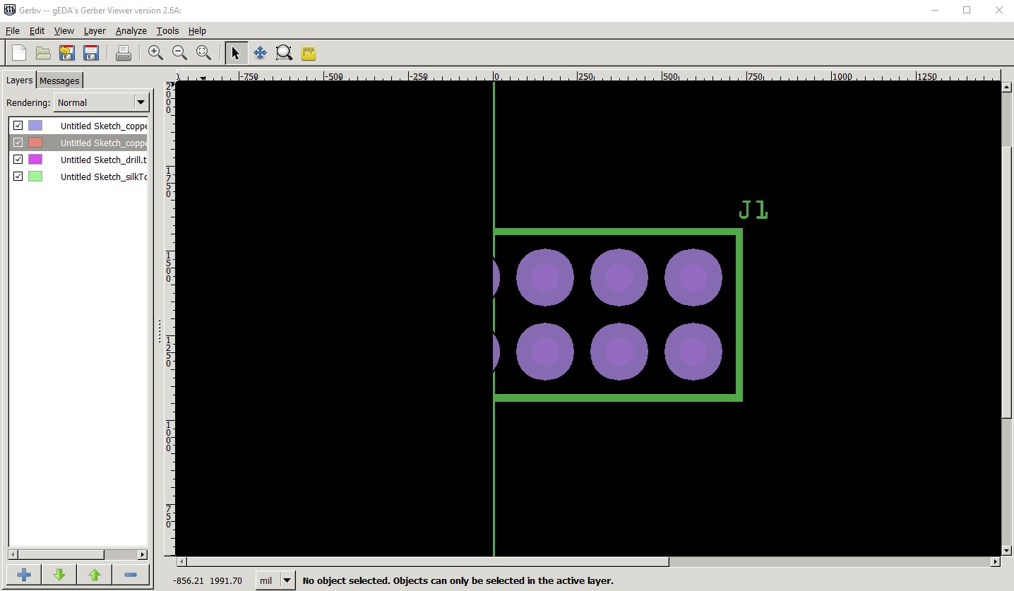
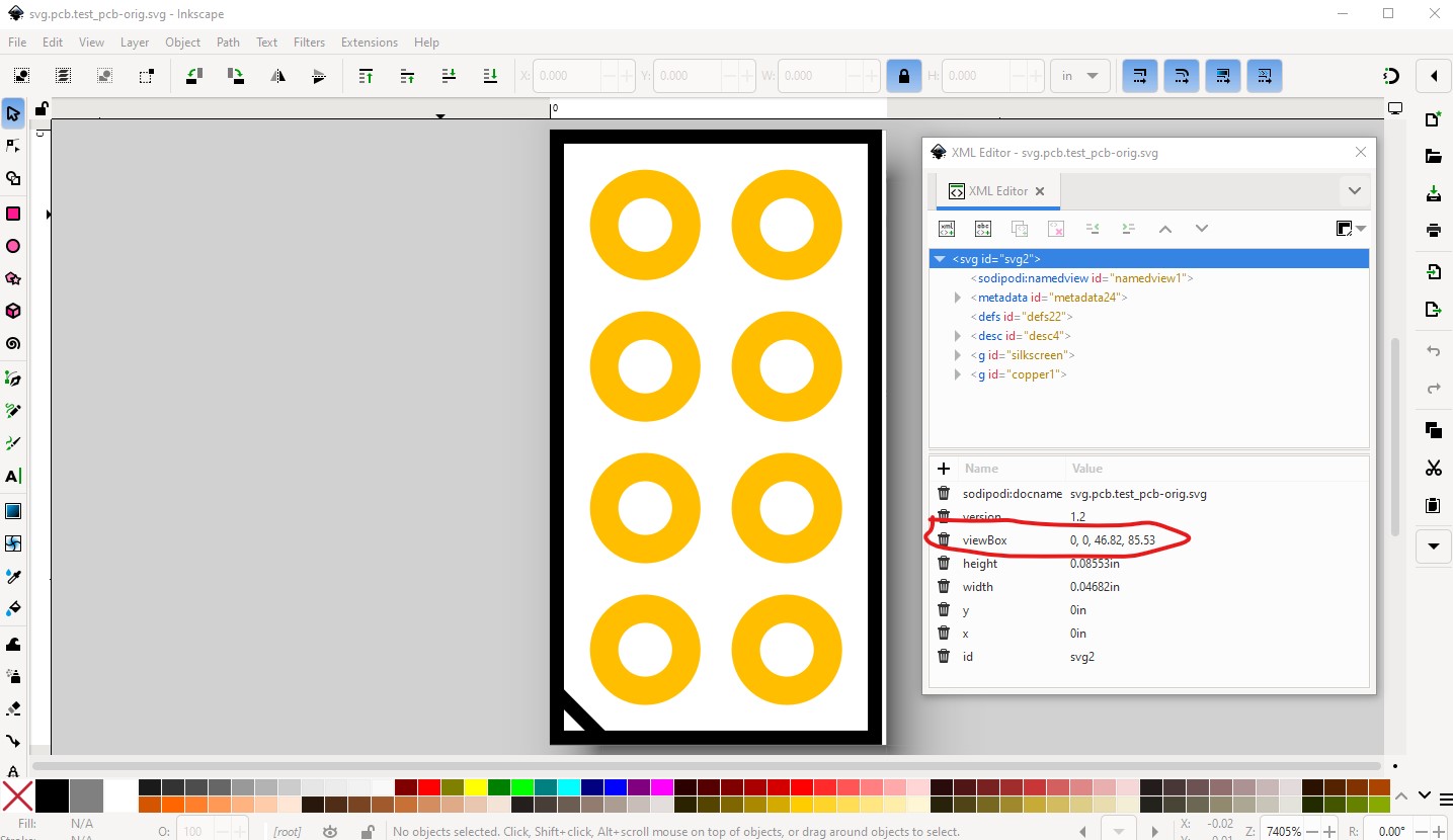
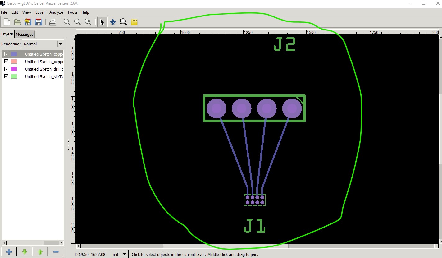
From the gerber output I am seeing I expect I have a viewbox calculation problem. I expect the view box is being offset for some reason as the gerber output is truncated (this is the 2x4mm 0.5mm part’s gerber output):which indicates an offset origin value with truncation on the left although it otherwise looks correct:
OK after a bunch of head scratching (initially I thought I had triggered a bug in gerber processing, but it turns out to be an svg error I made!) I have made progress. By mistake in the script I put commas in the view box setting so the viewbox in the parts above looks like this in Inkscape (with commas in the viewbox definition)
I would probably not have found this except that I ran the part through FritzingCheckPart.py and that flagged extra characters in the viewbox (I think the first time I have ever seen that error as Inkscape won’t produce it!) That doesn’t appear to bother the Fritzing renderer but does appear to break gerber processing. In fritzing pcb view the part looks fine (and I didn’t try the gerber processing until your post!)
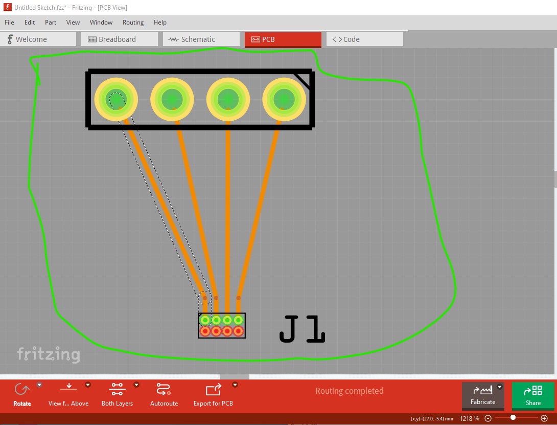
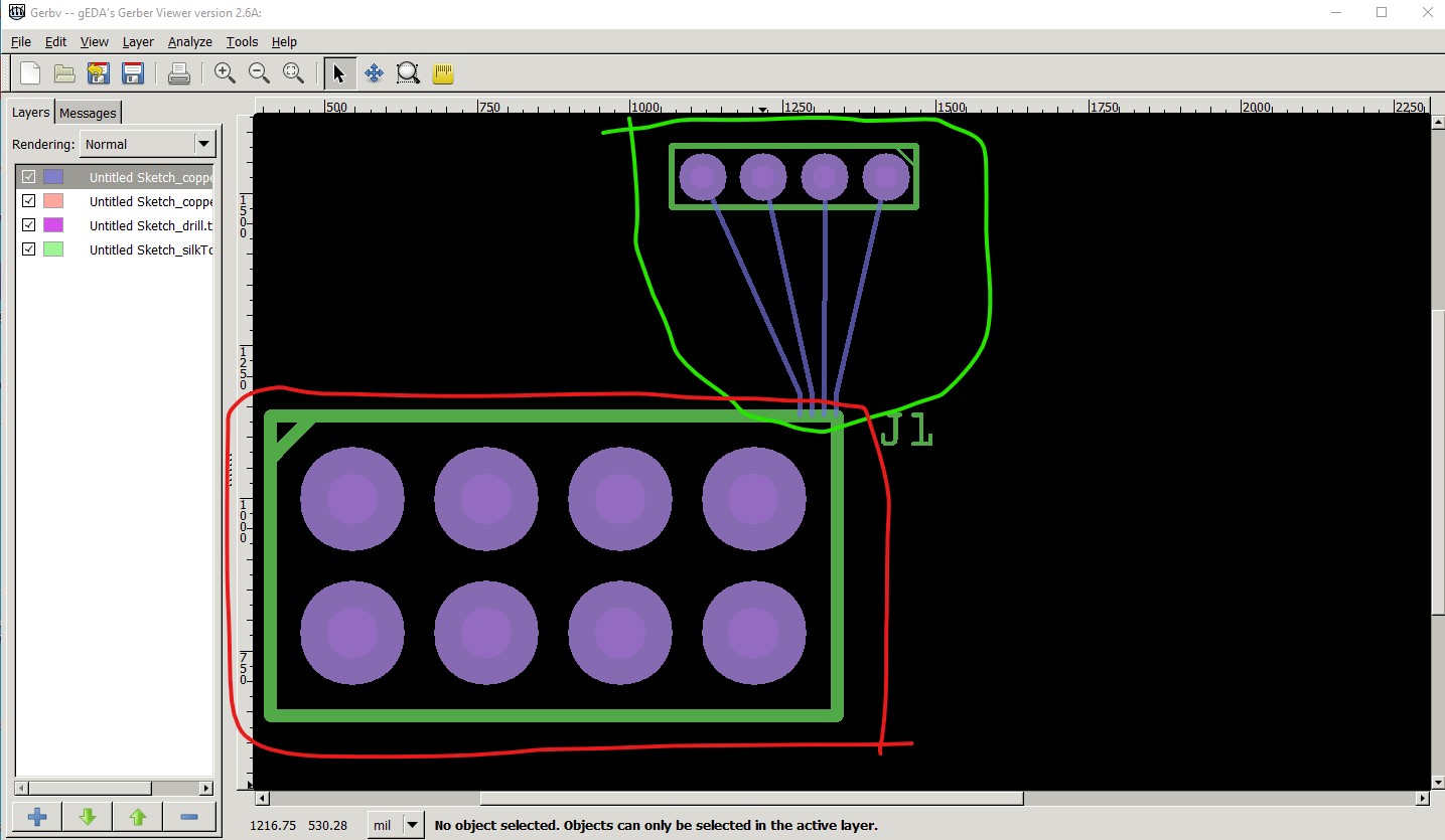
But the gerber output is wrong, this is the gerber output from the above pcb sketch which has the extra commas in the viewbox. The gerber output is way larger than the 0.5mm pitch shown in the pcb view (presumably because of the commas in the viewbox!)
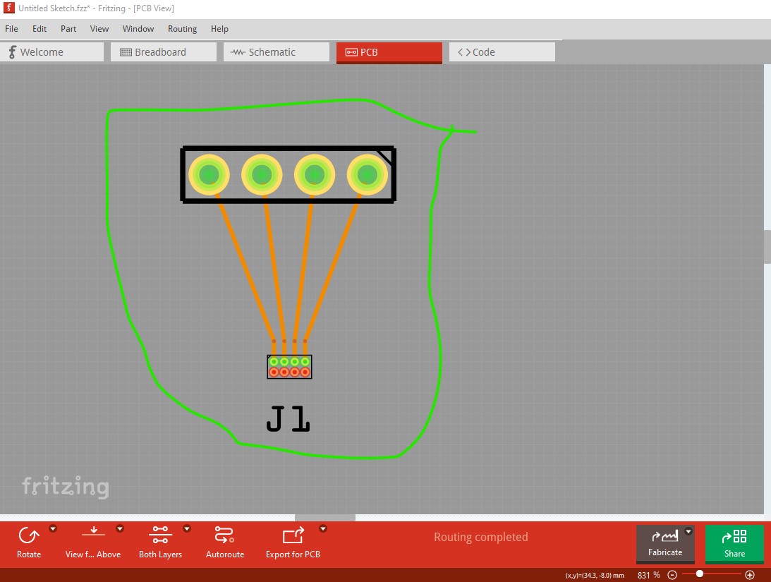
But a big change in gerber output which is now correct (as it was when I resized the pcb svg with Inkscape which I now realize corrected the viewbox and thus allowed gerber processing to work correctly.
Now the gerber output matches what Fritzing is showing and all should be well. I still have some issues around the viewbox calculation and some more work to do in processing colors but at least things are getting better!