I’ve got my breadboard wired up well but I cannot seem to figure out what how to fix the missing connection that appears on my schematic view(Q2). How should I adjust my bb view so that both views are completely routed? EDIT: Since I cannot post more than one image here is a link to the bb view https://i.imgur.com/HpK6V6i.jpgLED Summative Schem1.fzz (18.1 KB)
Post the ,fzz sketch with the 7th button above.
See all those red bits on parts, well they aren’t actually connected. I think you also have a ratsnest running across Q2.
The easiest way if you can’t figure it out is to select all traces in SCH, delete them, check the BB is still 100% correct, and redo the traces again in SCH.
Hi
I just had a look at the .fzz sketch:
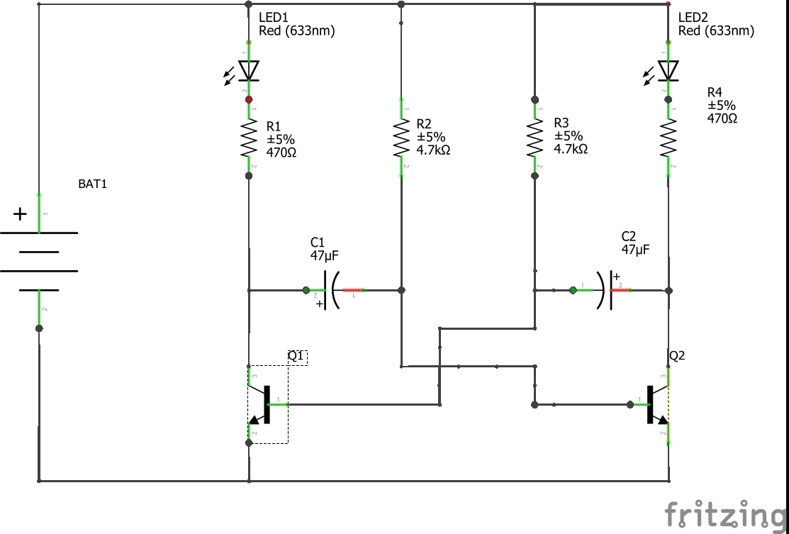
- In the schematic view there are in many places several lines on top of each other, re-doing some connections a few times (e.g. between C1 and Q1), making connections where one wouldn’t expect ones (e.g. the base of Q2 is connected to pin1 of C2, and pin 2 of R2 is connected to pin 2 of R3), and not making other connections that should be there (pin 2 of C2 is not actually connected to Q2).
- In the breadboard view the right pins of the capacitors don’t actually have contact to the hole in the breadboard. I don’t know how that happened, if I move them up one hole and down again then they do have contact.
- Not all of the wiring on the breadboard really makes sense. (What is the purpose of the wire between the lower pins of R2 and R3?)
My suggestion is to remove all the wires in the schematic view, clean up the breadboard view (also make sure that no component has legs marked in red), and then re-do the schematic view.
Please ask again if you have further questions.