Binding Posts (AKA Banana plug jacks, AKA Speaker Jacks)

I am looking for binding post jacks. Pictures below. These are the connectors you find on multimeters. They are also sometimes called banana-plug jacks. They are perhaps the same as speaker jacks, but I don’t have first-hand experience.

I am looking for a top-down view, so basically it would just be two concentric circles, with a metallic color in the middle and the post’s color on the outside. There would also be a tap with a connection point. I’ve never made a part before, but if no one else out there has made one, then this may be a simple one to start with. However, it seems to me that I’m probably not the first person to need this part.

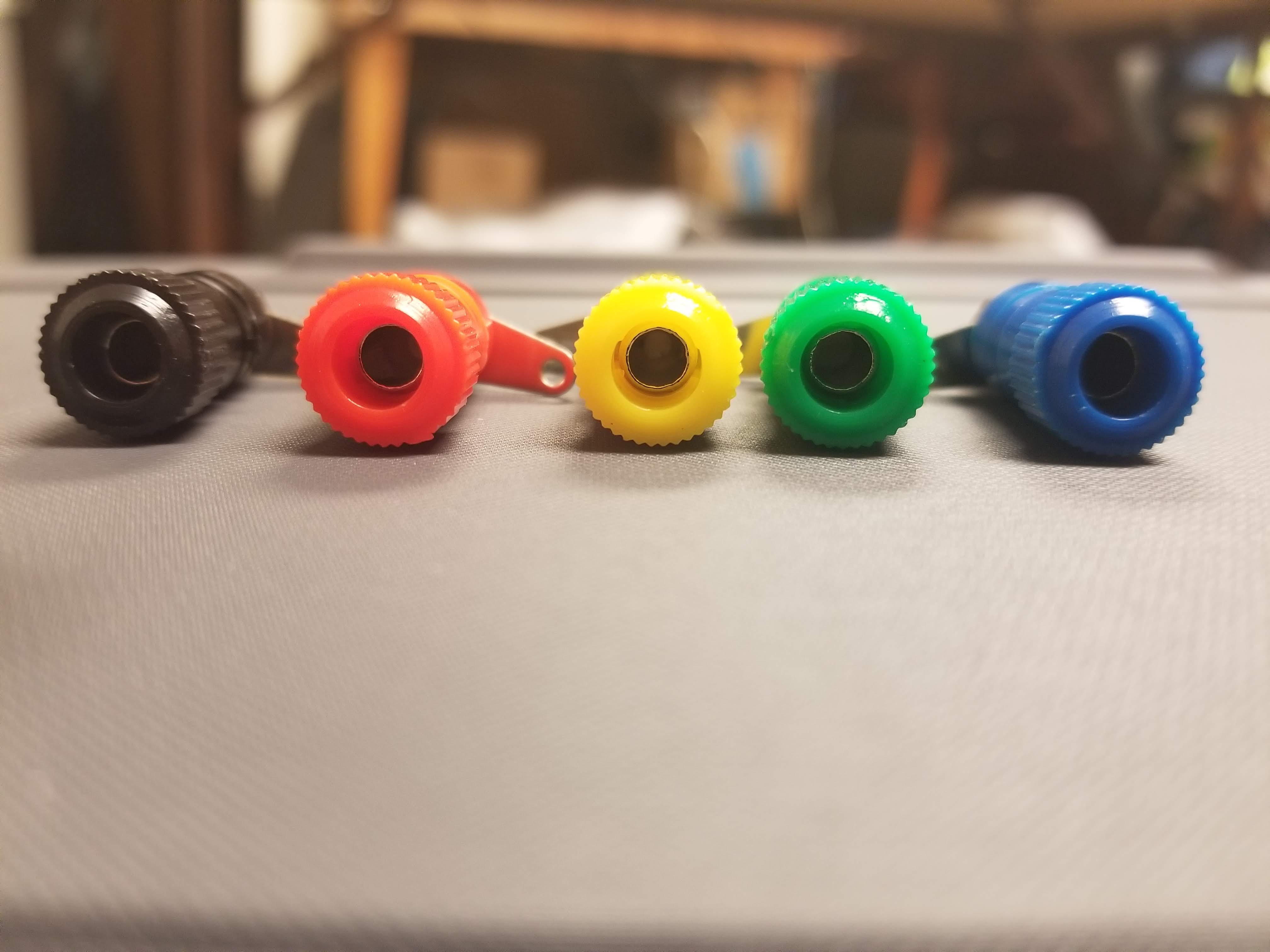
There is a standard view set in core parts in the Sparkfun section but no top view parts that I could find. They are however easy enough to make so here is a set.

top-view-banana-jack-black.fzpz (3.7 KB)

top-view-banana-plug-black.fzpz (4.0 KB)

top-view-banana-jack-blue.fzpz (3.7 KB)

top-view-banana-plug-blue.fzpz (4 KB)

top-view-banana-jack-green.fzpz (3.9 KB)

top-view-banana-plug-green.fzpz (4.0 KB)

top-view-banana-jack-red.fzpz (3.6 KB)

top-view-banana-plug-red.fzpz (4.0 KB)

top-view-banana-jack-yellow.fzpz (3.7 KB)

top-view-banana-plug-yellow.fzpz (4.0 KB)

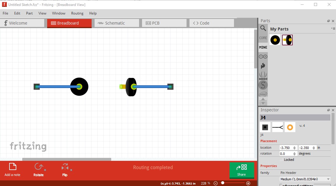
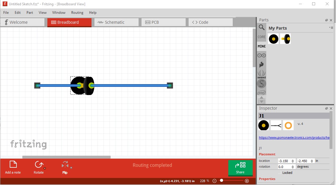
They are somewhat odd in that I chose to allow the plug to auto connect to the jack if you associate them correctly in breadboard. Here is an example:

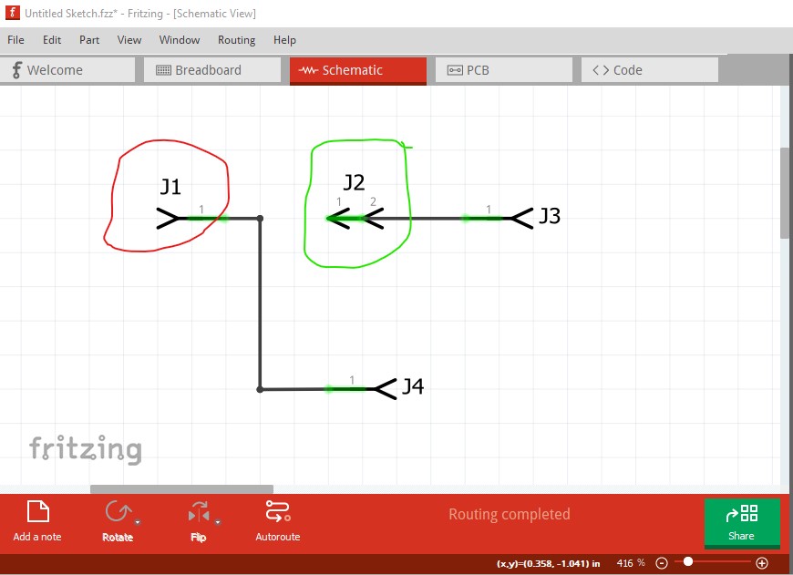
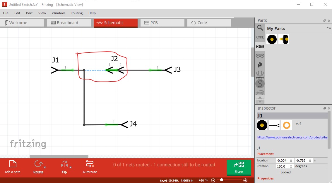
here wires and a .1 header connector have been connected to a black plug and jack (both of which fit within the board space taken by the real connector to make them top view!) At present that looks like this in schematic:

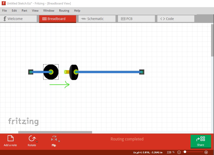
here the jack is circled in red (and has one connection) and the plug is circled in green (and has two bused together connections, one to connect to the jack and the other to the associated wire.) If I now move the jack (not the plug, due to a Fritzing oddity!) over the jack like this:

to get this

in schematic (and pcb) there is now a connection from the jack to the plug.

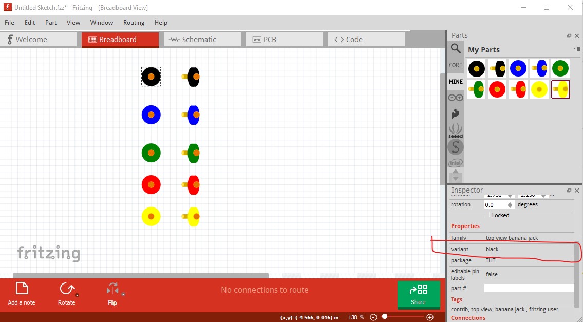
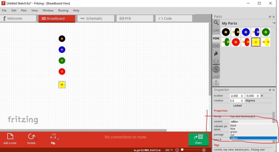
One other oddness. With the parts loaded in to the mine parts bin but not saved, the variant field in Inspector is not active (which is a reported Fritzing bug)

note despite all the parts being loaded the variant field in Inspector is greyed out. However if I save the parts and the mine parts bin and restart Fritzing I can now correctly select between the colors in Inspector

Peter

Looking for something similar. I bought these banana jacks that are designed to be PCB mount.
https://www.newark.com/multicomp/24-243-1/pcb-socket-4mm-red/dp/80P3616

The plug comes in from the side and there are two pins that mount in the board.

The web site appears to have CAD drawings for several platforms (see the UltraLibrarian photo link) but not one for Fritzing. I’m not concerned about what the part looks like in breadboard view, but want to get the hole sizes and spacings right for the PCB.

I’m new to Fritzing and have not yet played with the Parts Editor. Is there an easy way to use the existing CAD files for this part?

@ vanepp These are perfect! Far better than my nearly non-existent skills could have produced. They are exactly what I needed.

BTW, either something is truncated or you forgot to upload the red pair. I see them in your screenshots but not in the listed files.

Thank you so much. You have saved me hours/days of frustration,

TheSpiffer There is a utility to import parts from Eagle:

I’ve never worked with it. I just know it exists.

Yep I missed the red pair. I just added them in to the original post.

Peter

This should do what you want. The pcb hole size is set to 0.06in (slightly larger than the 1.3mm pin size) so checking that the pin will fit in a 0.06in hole (along with printing out the pcb footprint at 1:1 scale and checking it against a real part!) would be a good bet before ordering boards.

edit: replaced with a part with a 0.078in hole to provide adequate clearance.

multicomp-24.243-banana-jack.fzpz (3.9 KB)

While Eagle2Fritzing is available and I have a copy, it is easier in this case to just make the part from the datasheet. Eagle2Fritzing requires you have a Fritzing development environment to build it, and was meant for expert parts creators and thus requires a lot of experience making parts to use successfully.

Peter

Printed out the part footprint. That’s exactly it. Can’t thank you enough!

Sean

One more small request, if you can. The PCB hole size needs to be a little bigger. I took your advice and drilled some small holes in a piece of aluminum. The pin fits nicely through a 5/64 inch hole (0.078 inch), but it does not fit through a 1/16 inch hole (0.0625 inch). The pin has a somewhat rectangular shape, so the diagonal of that rectangle is bigger than the 1.3 mm specified in the data sheet.

Thanks again for your help!

Sean

Done. I just replaced the part with one with 0.078in holes.

Peter

Awesome! Many thanks!