Hello! just modified a regular transistor to the odd pin configuration of the BF199 used in radioamateur
72! CX5AA
BF199.fzpz (5.8 KB)
Hello! just modified a regular transistor to the odd pin configuration of the BF199 used in radioamateur
72! CX5AA
BF199.fzpz (5.8 KB)
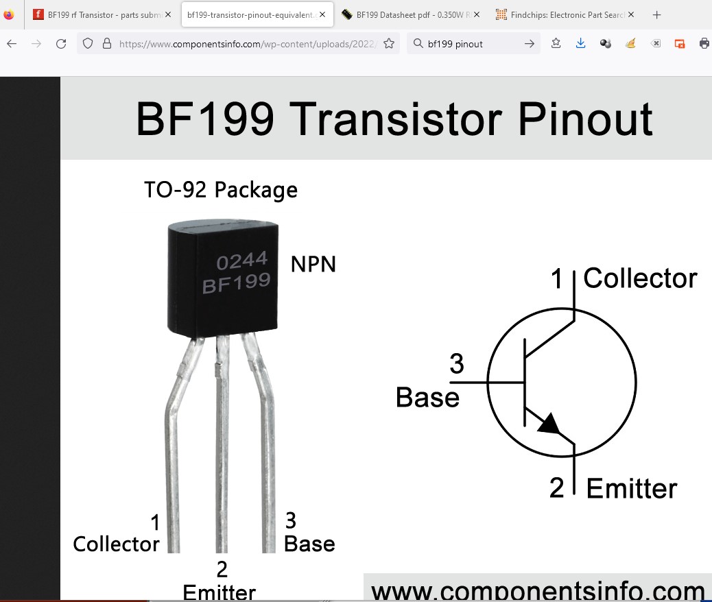
Some issues (but you managed to not mangle the bendable legs, so points to you!) Using this pinout
The fzp file should look like this
The spice pin numbers may need to change. I suspect this is for the pin out you started from and thus the pinout is likely wrong. Unfortunately I don’t know how the spice pins are defined so figuring out what is correct is likely to be an issue ![]() .
.
 <spice>
  <model>*Typical bipolar transistor </model>
  <model>.MODEL NPN_GENERIC NPN ()</model>
  <line>Q{instanceTitle} {net connector2} {net connector1} {net connector0} NPN_GENERIC</line>
 </spice>
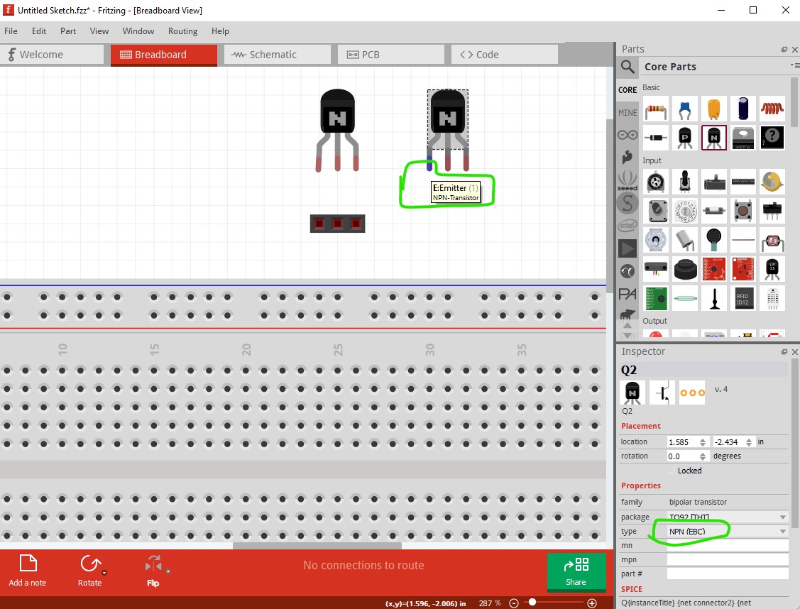
This looks to be for an EBC transistor (the default npn) so if we assume breadboard is the layout E is connector0 B is connector1 and C is connector2. So presumably this should change to CEB 2 0 1 like this (but I’m not sure of that!)
<line>Q{instanceTitle} {net connector2} {net connector0} {net connector1} NPN_GENERIC</line>
perhaps someone who knows the spice definitions will comment?
and the connector definitions should change to this
     <connectors>
      <connector id="connector0" type="male" name="C">
       <description>Collector</description>
       <views>
        <breadboardView>
         <p layer="breadboard" svgId="connector0pin" legId="connector0leg"/>
        </breadboardView>
        <schematicView>
         <p layer="schematic" svgId="connector1pin" terminalId="connector1terminal"/>
        </schematicView>
        <pcbView>
         <p layer="copper0" svgId="connector0pin"/>
         <p layer="copper1" svgId="connector0pin"/>
        </pcbView>
       </views>
      </connector>
      <connector id="connector1" type="male" name="E">
       <description>Emitter</description>
       <views>
        <breadboardView>
         <p layer="breadboard" svgId="connector1pin" legId="connector1leg"/>
        </breadboardView>
        <schematicView>
         <p layer="schematic" svgId="connector2pin" terminalId="connector2terminal"/>
        </schematicView>
        <pcbView>
         <p layer="copper0" svgId="connector2pin"/>
         <p layer="copper1" svgId="connector2pin"/>
        </pcbView>
       </views>
      </connector>
      <connector id="connector2" type="male" name="B">
       <description>Base</description>
       <views>
        <breadboardView>
         <p layer="breadboard" svgId="connector2pin" legId="connector2leg"/>
        </breadboardView>
        <schematicView>
         <p layer="schematic" svgId="connector0pin" terminalId="connector0terminal"/>
        </schematicView>
        <pcbView>
         <p layer="copper0" svgId="connector1pin"/>
         <p layer="copper1" svgId="connector1pin"/>
        </pcbView>
       </views>
      </connector>
     </connectors>
To get all the pins in the correct order. At present breadboard is incorrect. This is the generic NPN transistor
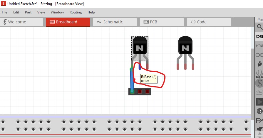
This is your transistor
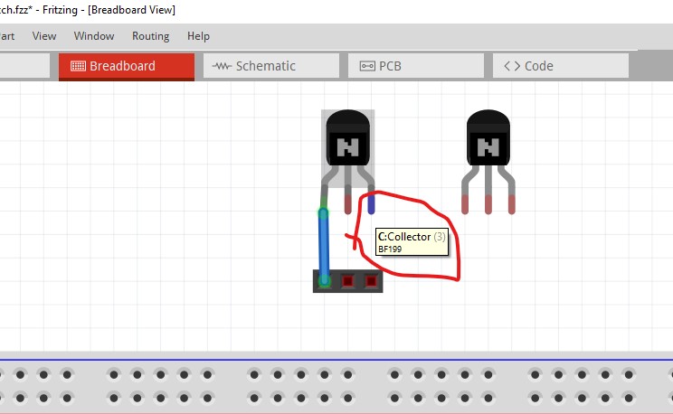
in breadboard the collector is showing as emitter. The emitter is showing as base.
and the base is showing as collector
The connectors if added to the .fzp file should fix that (and as noted may make spice work correctly as well, or may not ![]() ) As you may already know Parts editor doesn’t currently support bendable legs so you need to edit the underlying files to fix this.
) As you may already know Parts editor doesn’t currently support bendable legs so you need to edit the underlying files to fix this.
Peter