Two newbie questions:
-
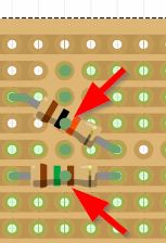
Cutting copper from a Fritzing stripboard is done between pads, whereas a generic rotary hand cutting tool physically removes a whole solder pad. The UX is somewhat misleading. What’s the best practice?
-
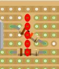
Where a part is placed over the top of a stripboard copper track cut, the cut is no longer visible. This could lead to assembly errors if a PDF file say is the reference. What’s the best practice? At present I have created a “cut pad” part which I copy over each copper cut (you can see two examples below - green dot over each resistor), but the color is out of my control & seems a bit hacky.
Thanks for any help.