I have attached a Fritzing file here: bewaesserung.fzz (389.5 KB)
Can you please tell me whether or not the wiring is okay? At this point, I do not care about the layout so much. I will manually solder this onto a universal breadboard… I just would like to know if it will work like this, or if I have to change something.
I will use ESPhome and should have no problem building the code itself. I currently have two Wemos D1 Minis do this already (one controlling the relay, one reading measurements from the HC-SR04s; no lux or temp sensors yet, I was just going to include them in the new version). These two separate devices work fine, but I think it’d be nicer to have everything controlled by one single device; if it works, I might even finally try etching my own board for this project.
I do not know the specific parts you are using, but if the labels on the pcb are correct, you have power and ground reversed for the relay. Which may not matter. Unless you end up “trusting” the labeling and run a connection from there to somewhere it DOES matter. Or if the relay has a diode across it to clip transients when power is disconnected. With all of the connections just running to headers, it is pretty hard to validate that it is electrically correct. It will depend on what is actually connected to the headers. For example, I can not tell if pin 3 of J9 is actually connected to the data pin.
If you want to ask about electrical functionality, you need to include those parts in the sketch. Laying out and routing the connections on the schematic view are generally a lot easier to check than the breadboard view. And Fritzing keeps/shows the connections created in one view in the other views.
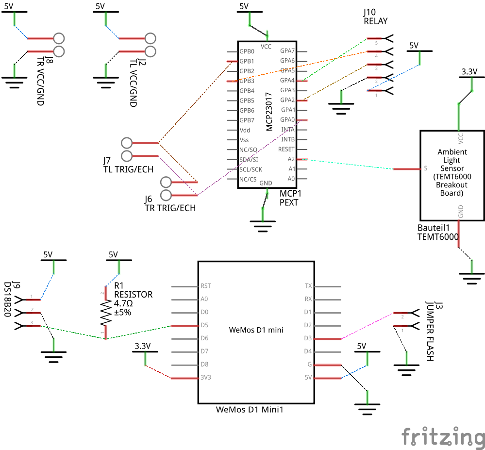
Here is a very quick, very rough, view of the schematic view with parts moved, rotated, flipped around to make viewing the connections easier. I added power and ground all over to reduce wiring clutter. I only actually added enough wires so that Fritzing would connect to the rest of the VCC and Ground symbols with the ratsnest wires. I also rotated and moved the part labels to keep them out of the way, and visually associated with the parts they belong to. Alignment was deliberately adjusted to keep the rats nest wires off of the vertical and horizontal, so that it is less likely to have one wire invisibly on top of another.
As a side note, the schematic view of the MCP23017 part could use some cleanup. The connection pins are missing terminalId elements, so the wires end up connecting to the middle of the pin lines, instead of the ends. Also, the connection pins are not aligned to the 0.1 inch spacing.
This is not the much of a problem, but thanks for pointing it out. The “relay” was just supposed to be male headers that I will manually connect to the relay board.
schematic view
Sorry. I left this out because I never had use for it. I am still learning all this and didn’t really see what this was used for. I’d usually use breadboard view to connect parts, and circuit view to wire things up, but didn’t (or don’t) know what schematic view is actually good for.
The MCP23017 part was a file I grabbed from the forums.
I tried manually building this project today on a diy THT board. It didn’t work as I forgot to power the MCP23017. But I was able to flash the software etc.; after connecting the MCP23017 to 5V and GND, nothing would work anymore. I couldn’t ping the device, nor read its logs. Will try again tomorrow, but perhaps I should just improve the sketch and have decent PCBs made, as I must have messed something up badly for this to suddenly stop working…
The only thing I see likely to cause the device to be unresponsive (other than ‘frying’ it), is something holding the chip in reset state, or, if it applies to this chip, something causing it to start up in programming/flash mode. What is that jumper flash header used for?
Polarity (plus and minus) matters in some cases, not others. Which is why I can not say much about whether the wiring will work or not. Bare headers do not show what is connected to each line. In general, it SHOULD work, but ONLY if the correct things are connected to each pin of the headers.
For the part, the quality of the part files downloaded from the forum can vary in quality. A lot. Some parts have been created because someone needed it for specific project, but were only interested in (say) the breadboard view. The rest was an afterthought, or not done at all. Which can cause problems when the part is later used by someone else beyond the scope of the original use case. Use «extra» care with those. When you get to using the pcb view to actually create boards, ALWAYS verify the generated output. The core parts are not all perfect either, and there are bugs in the code that can cause the generated output (gerber files) to be incomplete or have errors.
For schematics, here are a couple of places to start.