Before working on the routing (which is easily doable in Fritzing, no need of Kicad or Eagle) a couple of technical issues about power.
edit:
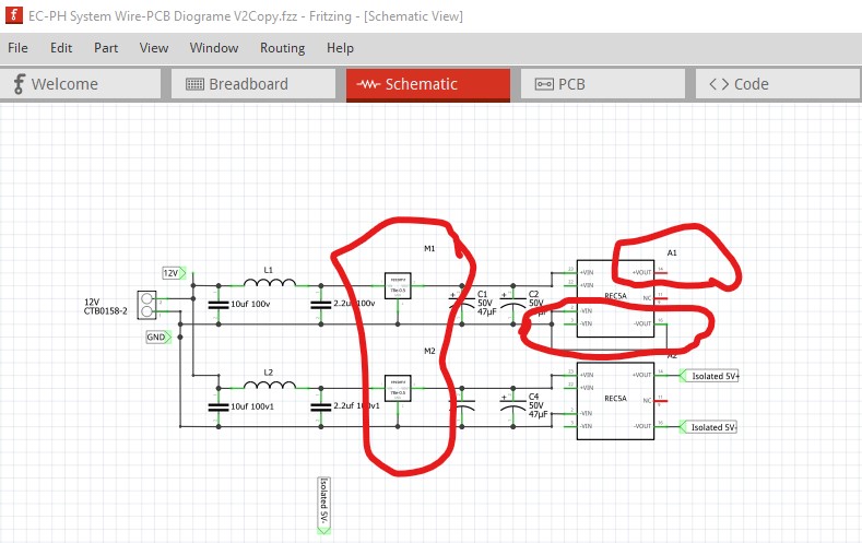
I see I misread the part I thought was a 7805, it is already a switching regulator, but only has a 0.5A output current. That seems a bit close to the limit given the projected current draw, but if the pro minis aren’t drawing as much current as I think it may be OK. I would still eliminate one REC5A to save space as it doesn’t seem to be doing anything useful though.
Your latest one is missing the non isolated power output connection (+vout doesn’t go anywhere) in schematic and thus pcb. As well that REC5A isn’t doing anything useful (as it is not isolated) and thus only takes up space and adds an additional point of failure. After that I have concerns about the 7805s and the maximum current draw. As I recall the pro minis each take about 300ma which implies almost 1A (the limit of a 7805) of current draw. The relays would be an additional problem except they are on the isolated REC5A. It looks like they are around 80ma per relay (off the digikey site as it isn’t in the relay data sheet!) so the 5 relays are taking about 400ma. That means the 7805s are running a reasonably large amount of current from a 12V input and will thus be getting hot (as they are linear regulators.) I’d suggest replacing both 7805s with one of these switching regulators:
which has a Fritzing part as you see. It is good for up to 2A and is about 80% efficient, but they are noisy and it looks like you have EMI concerns from the input filtering, but I would use one to replace both 7805s and one of the REC5As to save some space and add reliability. There are lots of other buck mode switchers as well (some with a fixed 5V output, these are adjustable.) The 7805s will shut down if they get too hot, so you may find the board stops working at high ambient temperatures with the 7805s. After that there is a problem with the relay part in schematic: the pins are a bit misaligned in schematic. I can fix that up so that schematic looks better (it will only make a cosmetic difference electrically it works now!)
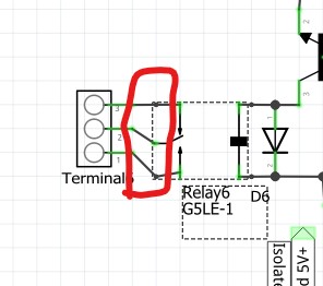
The relay pins should align to the 0.1in grid in schematic.
Peter