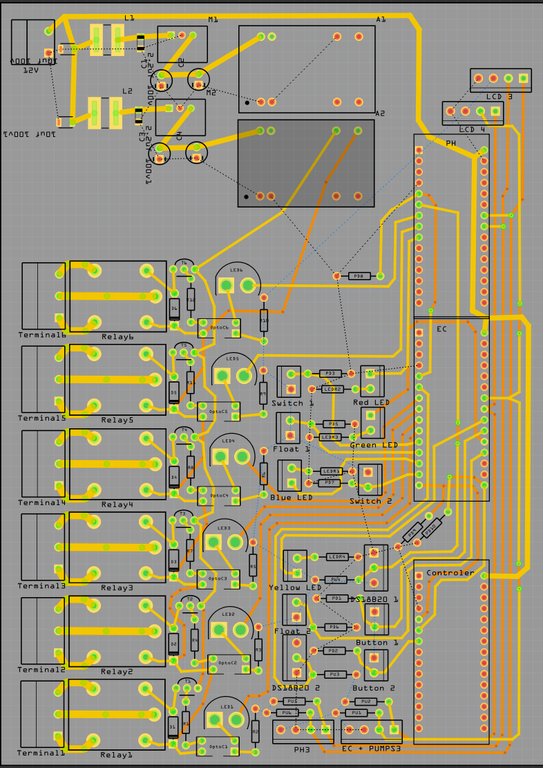
hello everyone this is my first PCB im making its a little complicated but it is basically a bunch of digital signal lines to control 3 Arduinos some relays, 2 LCDs, and a few inputs like 2 I2C and a temperature sensor and float switches some lines have pull-down resistors and the I2C have pull-up resistors and the leds have 220 ohm resistors. I have a working contraption but its 3 Arduino unos hot glued to cardboard with the relays glued beside it and a mess of wires connecting it. i was hoping to make it look neat and more presentable but im limited to (7inch 178mm high) and (5inch 127mm width) for the PCB. I have made most of the PCB just not the 5V + - i was planning on using ground fill to make a 5v+ plane on the top and a GND plane on the bottom but all the traces make the plane cut up and not fully connected. i dont know if it would be ok to make trace connecting the ground fills or should i run a dedicated 5V + - trace for the whole broad if so any tips to make it fit?
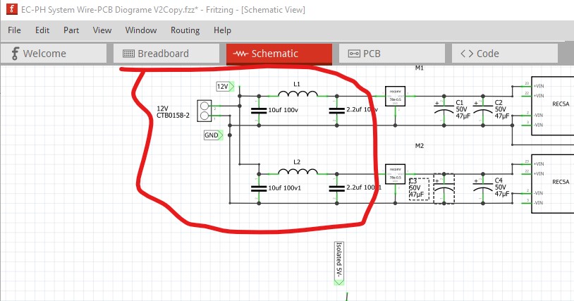
the Diagram should be good as well but i do have one problem i have not fixed yet. there is a rats-nest line connecting L1 witch is not right but when i delete it it removes the 12V power tag to the arduino vin, but i think it is ok to ignore
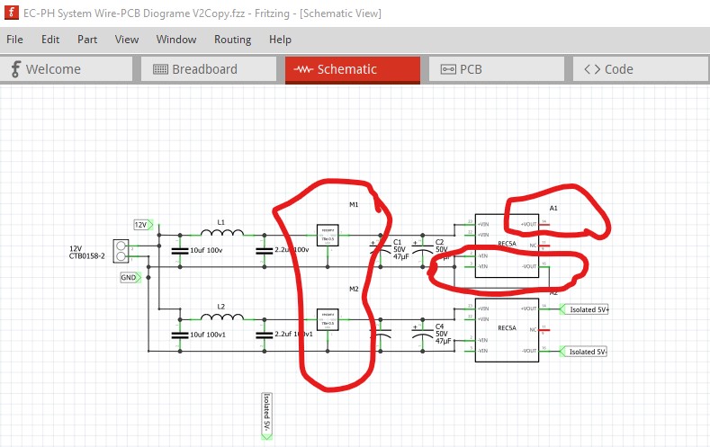
I see I misread the part I thought was a 7805, it is already a switching regulator, but only has a 0.5A output current. That seems a bit close to the limit given the projected current draw, but if the pro minis aren’t drawing as much current as I think it may be OK. I would still eliminate one REC5A to save space as it doesn’t seem to be doing anything useful though.
Your latest one is missing the non isolated power output connection (+vout doesn’t go anywhere) in schematic and thus pcb. As well that REC5A isn’t doing anything useful (as it is not isolated) and thus only takes up space and adds an additional point of failure. After that I have concerns about the 7805s and the maximum current draw. As I recall the pro minis each take about 300ma which implies almost 1A (the limit of a 7805) of current draw. The relays would be an additional problem except they are on the isolated REC5A. It looks like they are around 80ma per relay (off the digikey site as it isn’t in the relay data sheet!) so the 5 relays are taking about 400ma. That means the 7805s are running a reasonably large amount of current from a 12V input and will thus be getting hot (as they are linear regulators.) I’d suggest replacing both 7805s with one of these switching regulators:
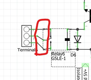
which has a Fritzing part as you see. It is good for up to 2A and is about 80% efficient, but they are noisy and it looks like you have EMI concerns from the input filtering, but I would use one to replace both 7805s and one of the REC5As to save some space and add reliability. There are lots of other buck mode switchers as well (some with a fixed 5V output, these are adjustable.) The 7805s will shut down if they get too hot, so you may find the board stops working at high ambient temperatures with the 7805s. After that there is a problem with the relay part in schematic: the pins are a bit misaligned in schematic. I can fix that up so that schematic looks better (it will only make a cosmetic difference electrically it works now!)
The relay pins should align to the 0.1in grid in schematic.
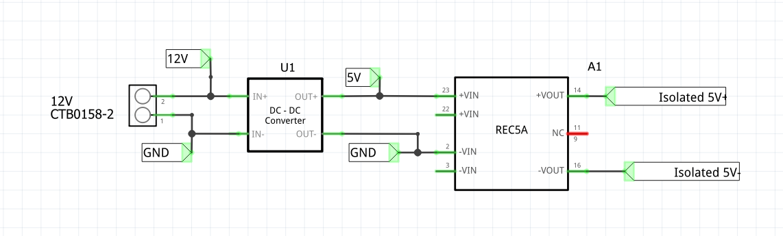
OK Thank you that sounds grate, I was original looking at that Mini-360 DC-DC converter but i did not know how to mount it to my PCB as it is already a separate PCB but if that little thing will replace all my current mess then i think il find a way, maybe i could i just use some male and female headers. Im very new to the technical specifics of electronic making I just know some basic theory so I copped the typical application part from the data sheets to make that circuit so im assuming that the EMI filtering your referring to is the capacitors? and i did not know if they where optional i also wanted to replace the SMD MLCC with THT ones but did not know if it would affect the circuit.
So to make the new circuit would take 12V into the Mini-360 DC-DC converter and then that is regulated 5V out? I can then run the Arduino Nanos with that and still use a REC5A to isolate the relay coil power?
Yes that should work fine. You do need to adjust the voltage output to 5V before installing it though, the Nanos are limited to 5V and more may damage them. There is a pot on the Mini-360 to set the output voltage. On the ones I have the range is a little odd, at one end of the pot range they don’t give any output voltage and I thought they were broken, but adjusting the pot through its range got them working and let me set 5V. Just feed the Min360 from the 12V source, then with a voltmeter on the mini-360 output adjust it to be 5V and you should be ready to go.
Yes, the inductors and capacitors are used to block EMI from getting back to the 12V source. If you don’t have an EMI compliance issue, you are both lucky and don’t need the components.
Switching from SMD to through hole shouldn’t make any difference and makes both assembly and pcb routing (because you can route from both sides of the board) much easier. I’m working on the relay part in core parts, (it is old and thus somewhat misconfigured) I’ll post a fixed up sketch in a while.