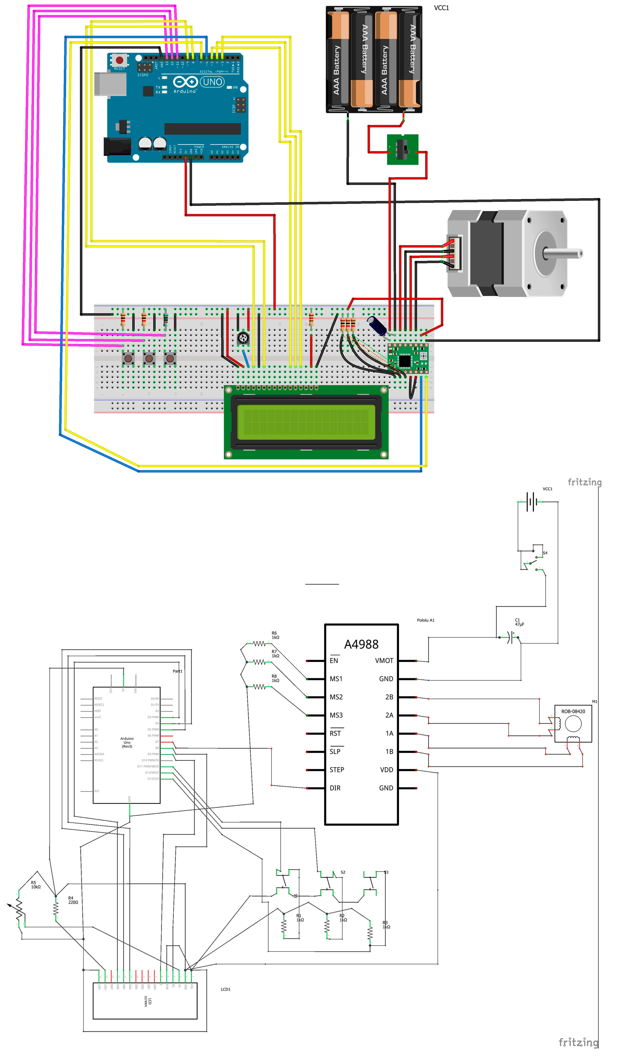
I’m building a barn-door astrotracker, and I’ve ordered a bunch of arduino parts for it. As preparation before the parts arrive, I’ve tried to set up a sketch on how to connect everything together. This is as far as I’ve come. With my extremely limited knowledge of electronics, I’ve probably done something wrong or missing something wires or something.
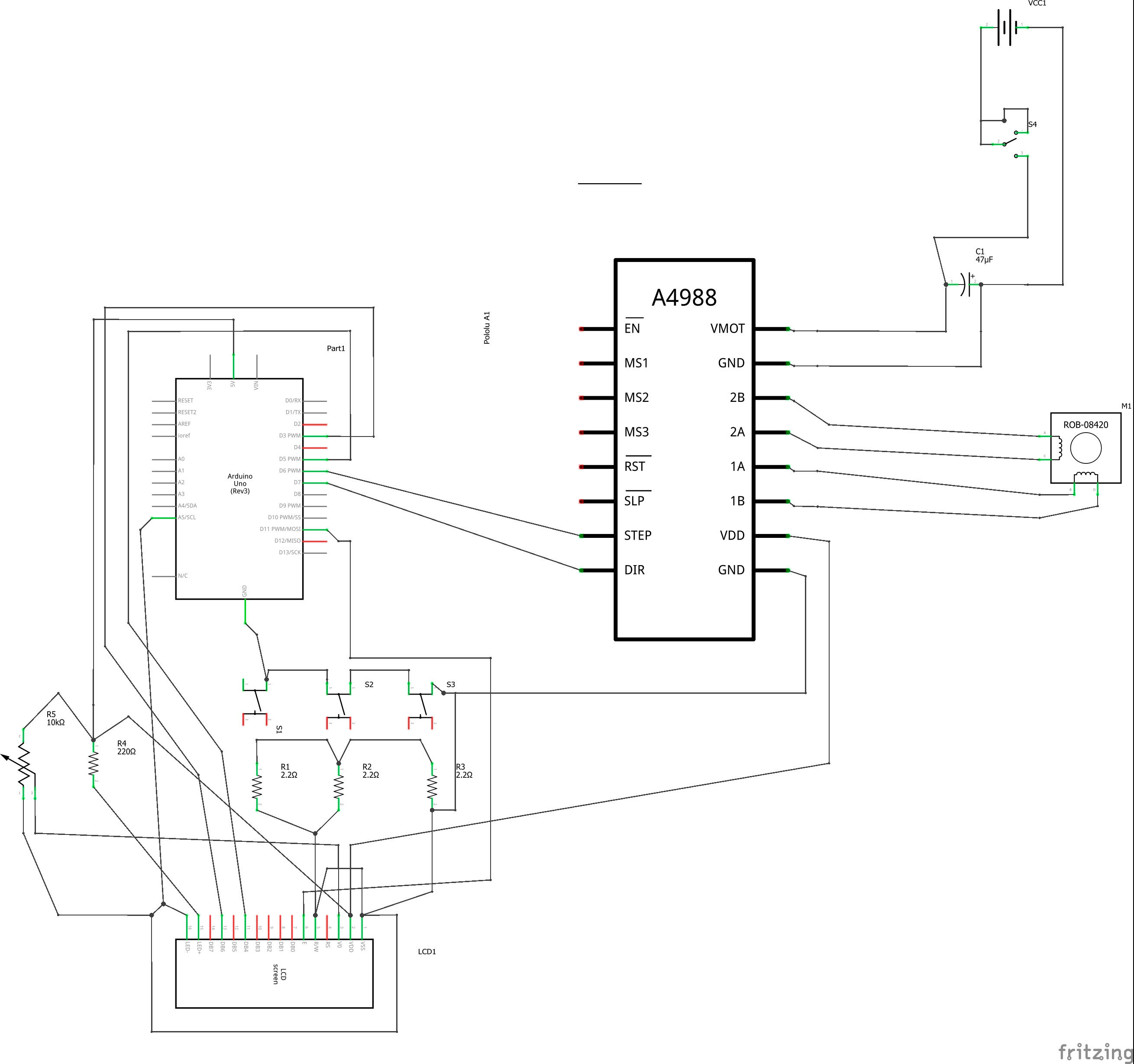
I think that you would be best to upload the schematic view of your proposed solution along with part numbers.
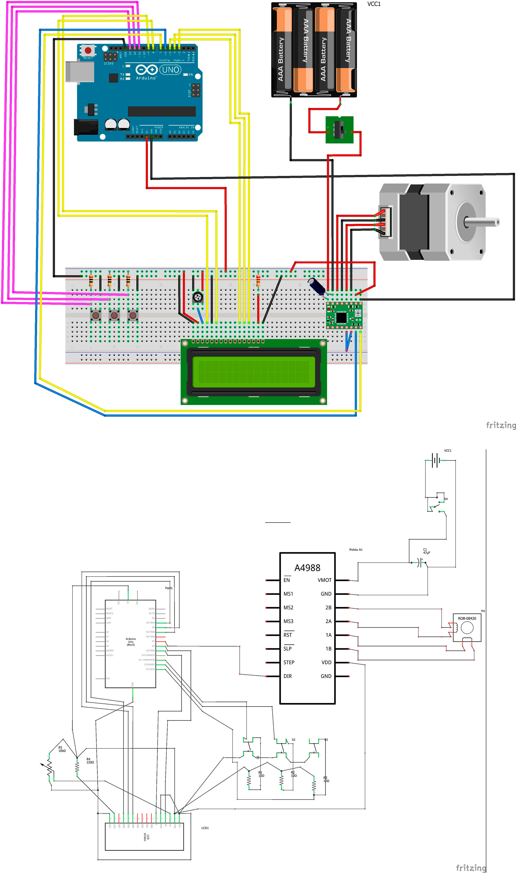
I assume the motor is a stepper motor and thus the board on the right of the breadboard is a motor driver and the
board by the battery is a power switch for instance but without part numbers its hard to do more than guess.
Your switch layout looks to me to be a little odd (assuming the 3 items on the left of the breadboard are switches of
course). I don’t see how you would tell one switch from another since there appears to only be two connections to
three switches. The LCD setup looks like it could be correct, 4 data wires, a grounded chip select, data/command
and write. Assuming that is a 5V Arduino UNO you need to make sure the LCD and stepper motor driver are either
also 5 Volt or at least have 5 Volt (as opposed to 3.3V) tolerant inputs. After that its all a matter of software probably.
Parts list:
Arduino UNO R3
A4988 stepper motor drive
NEMA 17 bipolar motor
16 pin LCD screen
3 pushbutton (Start, reset and pause button)
3 resistors 2.2ohm (for the pushbuttons)
1 resistor 220ohm (for the screen)
1 potentiometer (for the screen)
1 Switch (on off power switch)
1 capacitor 47µF
1 battery (8x AA batteries)
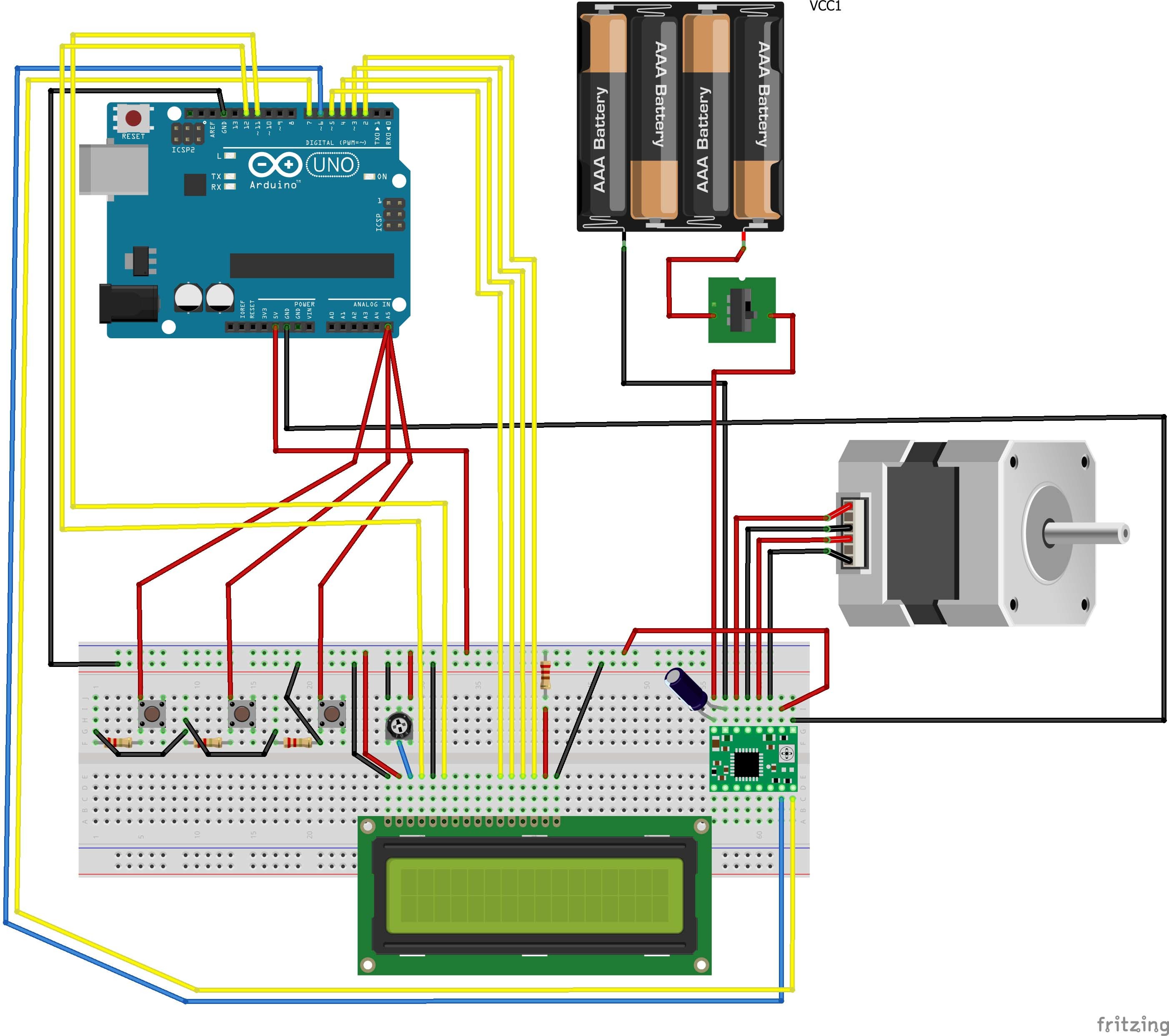
Indeed looks like a few problems there. Your push buttons likely won’t work like that. Each push button needs to connect to its own pin on the Uno so the software can tell which of the three is pressed. Basically one end of the push button goes to ground and the other contact connects to both an input pin on the UNO and a pull up resister to +5V. As well you need more connections to the A4988. If you only want full steps on the motor you could ground the EN, MS1, MS2, and MS3 pins if you want microsteps you would need to connect Uno digital output pins to MS1, MS2, and MS3. You need a pull up resistor to 5V (or a UNO output pin) on RST and SLP (a 1K resistor to +5V is probably best, I doubt you care about sleep mode). The LCD needs the wiper of the pot to go to pin 3 (not the backlight where it currently appears to go) and you need Uno pins connected to pin 4 (data/instruction select) and pin 6 (Enable) . The backlight looks to be connected directly between 5V and ground which will burn it out. The 330 ohm resistor needs to be between the lcd and +5V to limit the backlight current. If you have software for the Uno, then you need to assign the I/O pins on the Uno to the hardware on the pins which the software expects them or change the software to match your pin choices. Good luck!
I’ve giving it a try, but have some questions.
The buttons have been given each it’s own I/O pins. But you say [quote=“vanepp, post:4, topic:1971”]
a pull up resister to +5V
[/quote] I have a resistor that has 10ohm, is that enough? And correctly placed?
Now, you also say [quote=“vanepp, post:4, topic:1971”]
If you only want full steps on the motor you could ground the EN, MS1, MS2, and MS3 pins
[/quote]
With that you mean that those need to be connected to the ground wire?
Yes (although its a little small for old eyes :-)) the schematic for the switches looks correct. A 10 ohm pull up resistor would technically work but it will draw too much current. A 1k or even 10K resistor would be a more reasonable value (value isn’t all that important if they are high enough, if you already have 2.2K resistors they would work fine).
I was going to say the LCD is wrong, but then I looked more closely at the schematic and see that they have tied the write line high (so it never reads) which will indeed work and saves a pin so that should work fine (I did find it very odd that there would be an error on the Arduino site ).
As to the motor driver pins, yes they all need to be connected to either power or ground usually through a pull up or pull down resistor like the push buttons but a direct connection to ground or +5V if they need to be high will also work. In general CMOS inputs (and most stuff you will use is CMOS these days) should not be left to float (unconnected). They must be connected to either ground or vcc (3.3 or 5V typically) as noted usually via a 1K ohm resistor.
In this case without the enable pin being tied to ground (also known as tied low in case I slip and use that term) the motor driver won’t do anything as it is not enabled. Similarly the slp (sleep) pin must be tied high or the chip will go to sleep and not function. The reset pin needs to be either driven from an Arduino data pin (if you want to be able to reset the motor driver board) or tied to +5v (or through a pull up resistor to 5v) so the chip won’t be in reset and not function. The ms1/2/3 pins control step size setting them all to 0 will (from the data sheet I haven’t actually done this) cause it to take full steps and yes the means connecting them to ground, if you want microstepping for better resolution you would need to connect them to Arduino pins (and find the Arduino microstepping library, I’m pretty sure there is one).
One last thought is power to the stepper motor. Steppers are generally high current devices. That means they will tend to flatten your batteries fairly quickly. I’m assuming you have wall wart
power for the Arduino, you may want to consider replacing the batteries with a 6V wall wart (with a current rating appropriate for the stepper motor) to save battery cost. The batteries should work fine, they just may not last all the long.
I checked the kit I’m getting, and found out that I’m getting 1k ohm resistors. So I put those in. The higher the resistor the lower amount of power it uses?
I forgot to mention that I do have a battery pack that can run on either 7.4V or 12V and has (if I remember correctly) 5000 mAh capacity. Should be plenty for a night out, don’t you think?
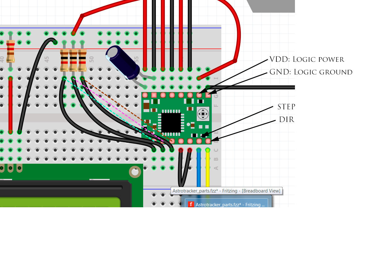
Closer but still a few problems (I just discovered I could download the schematic and blow it up in Infanview which makes looking at it easier!): the push buttons and LCD look fine, but the motor driver still have some problems. First the Gnd pin on the bottom right needs to connect to ground on the Arduino (there are two grounds on the motor driver, one for the motor which is connected correctly and one for the logic which currently isn’t connected). While they probably are connected together internally, current surges in the motor (which there will be) can affect logic ground causing problems, so using that as logic ground is a bad idea, so connect up the logic grounds by connecting the motor driver ground on the bottom right to Arduino ground. Then you are missing a connection from step on the motor driver to an output pin on the Arduino, the direction pin tells it which way to go, but it won’t do anything unless the step pin is pulsed to cause it to take a step. Then reset needs a connection, I’d use a connection to the Arduino reset pin., that way when the Arduino is reset so will the motor driver which is likely what you want. Then the en pin needs to be connected to Arduino ground and slp needs to connect to a pull up resistor (1K is fine) to 5 volts to disable sleep mode. That should do it
for the connections I think. As to the current question basically yes, the higher the resistance
the less the current for the same voltage. This is controlled by ohms law which says
I =E/R where I is the current, E is the voltage and R is the resistance. In the case of your
10 ohm pull up resistor to 5 Volts we get 5/10 or .5 amps of current (likely more than the Arduino 5V supply can deliver) for each button pushed, so pushing all three at once would try and take 1.5A! With a 1K pull up resistor that drops to 5 milliamps a much more reasonable current draw. As to the question of battery packs, that depends on how much current the stepper takes. Unlike a dc motor which only draws current when it is running, a stepper motor always draws current (to hold the motor in its current position). It isn’t uncommon for a big stepper motor to take upwards of 1/2 amp per phase which will flatten even a 5 amp hour battery
pack reasonably quickly. While in theory 5 amp hours should supply .5 amps for 10 hours in practice that time is usually less. Its going to be a case of try it and see I expect, you may end up having to put more batteries in parallel to get the time you want.
This multiple views thing will take some getting used to (I’m new to fritzing and haven’t used it a lot yet), I was looking at the schematic view (which as you note was incorrect) and didn’t think to check the breadboard view to see actual physical wiring. In addition with the wires physically connected as shown in the breadboard view you are correct it should work even though as old_gray noted fritzing doesn’t think they are correctly connected (yet another source of confusion).
Looks pretty much like you are good to go and now its only a small matter of software
This looks like a rewarding project… I did some research and saw some of the awesome pictures you can take yourself with this tracker and a high quality lens. They look like they were taken by NASA and the space telescope…
I finally got the parts I need. And I’ve started connecting everything together. But of course I got into a little trouble. When I connect the motor to the stepper board and connect power, the power cable gets really warm. Like smoking hot warm.
What is wrong?
Edit: I figured it out. Was using a ball switch instead of a capacitor… The kit I got don’t have a capacitor in it. So need to find one.
Olá! Estou produzindo um Astrotracker com base neste projeto. Gostaria de saber se ele funcionou e qual o código de programação.
Agradeço de puder responder.
Obrigado!

 ).
).