does anyone have this part in fritzing or something that works the same?
AZDelivery 2 Kanal Relais Modul 5V DC Solid State Relais Low Level Trigger Power Switch

does anyone have this part in fritzing or something that works the same?
AZDelivery 2 Kanal Relais Modul 5V DC Solid State Relais Low Level Trigger Power Switch
This part should do what you want.
2channel-solid-state-relay-module.fzpz (13.8 KB)
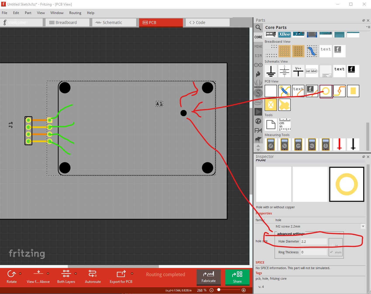
Note while it has pcb view it is somewhat odd. Due to the screw terminals the control pins end in pads (and the load pins don’t appear in pcb at all.) The intent is that a wire should be soldered in to the pad and run to the screw terminal on the module. As well the mounting holes are not drilled by default. To get mounting holes you need to drag a hole from core parts/pcb in to the sketch then set the size appropriately like this:
Then move the hole over the hole in silkscreen and a hole will be drilled in the pcb.
Peter
Hello Peter,
Do You have a 4 channel version too?
Gruß Jörg
Good morning,
Unfortunately, Peter has passed away.
I could give it a try, but I certainly won’t match Peter’s quality.
Do you have a link to the 4-channel version?
Best regards, Harald!
Hi Harald,
I’m sorry about that.
I found one, but there’s a connection that’s wired incorrectly.
omron-relay-module-4way.fzpz (16.7 KB)
Ch3 is wired incorrectly there. Maybe you can figure it out. I spent half an hour yesterday trying to fix it myself.
Regards,
Jörg
Hi Jörg,
Great, I think I can get that done quickly.
I’ll get back to you!
Cheers, Harald!
Hi Jörg,
I can’t find the error. CH3 is connected to the CH3 graphic, isn’t it?
Can you describe the error in detail or send a screenshot?
I created an example file, and everything looks fine there.
Beispiel.fzz (38.5 KB)
Best, Harald!
it doesn’t make sense to connect ch1 to ch4 twice since they are the same inputs
simplesample.fzz (35.6 KB)
if you look at my example, the connections are distributed arbitrarily
Well, the channels CH1-4 are internally connected to the PINs.
If you now select CH1 on the terminal and then solder the module onto a PCB, the PIN CH1 would have no connection to the terminal CH1. In the original component, however, it does have this connection.
But the component actually behaves strangely. This could be because it’s still waiting for 14 more connections. I’ll need to take a closer look at the fzp file for that.
Would it also be an option for you to skip the PCB view entirely? Then I can do it the same way as with the 2-channel relay.
Best, Harald!
Hey Harald,
so I don’t actually need the PCB view.
But I also just noticed that you can simply create the connections directly on the breadboard and then it works fine.
So we can leave it as is.
Beginner’s mistake, sorry!
Cheers
Jörg
Yes, good. Otherwise I would have removed the internal connections and set the PCB view to “nonconn”.
But this way works too, I suppose.
Best regards, Harald!