Hi,
I am looking for an Atmega328p-mu part.
When I select Atmega328 I cannot find a matching qfn variant. There is qfn44, where as I need a qfn32 (32 pins). Also, how can I see the dimensions for the chip?
I am also wondering whether to pick a qfn or tqfp form. I will do the sodering using a stencil, just if you have some experience you would like to share.
Thanks in advance.
Jakob Doepping
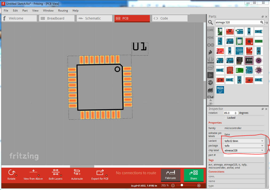
Welcome aboard! If Fritzing if you drag the 328 in to a sketch and then use Inspector (the lower right window) you can select a 328 in a 32pin SMD package:
to check the footprint you can either print pcb out at 1:1 scale and compare it to a real chip or use a SVG editor such as Inkscape to examine the footprint svg file. In this case that file can be found at
your-fritzing-install-directory/fritzing-parts\svg\core\pcb/sparkfun-digitalic_tqfp32-08_pcb.svg
which at a quick glance looks different than the one in the 328 datasheet, although there also is not a -mu (only MA and PN packages that I can see) so you would need to find the footprint for the -mu package if it is different. It isn’t a big deal for me to modify the current footprint if you need something different (the same may not apply to you  ) but I need the dimensions you need to do so.
Peter
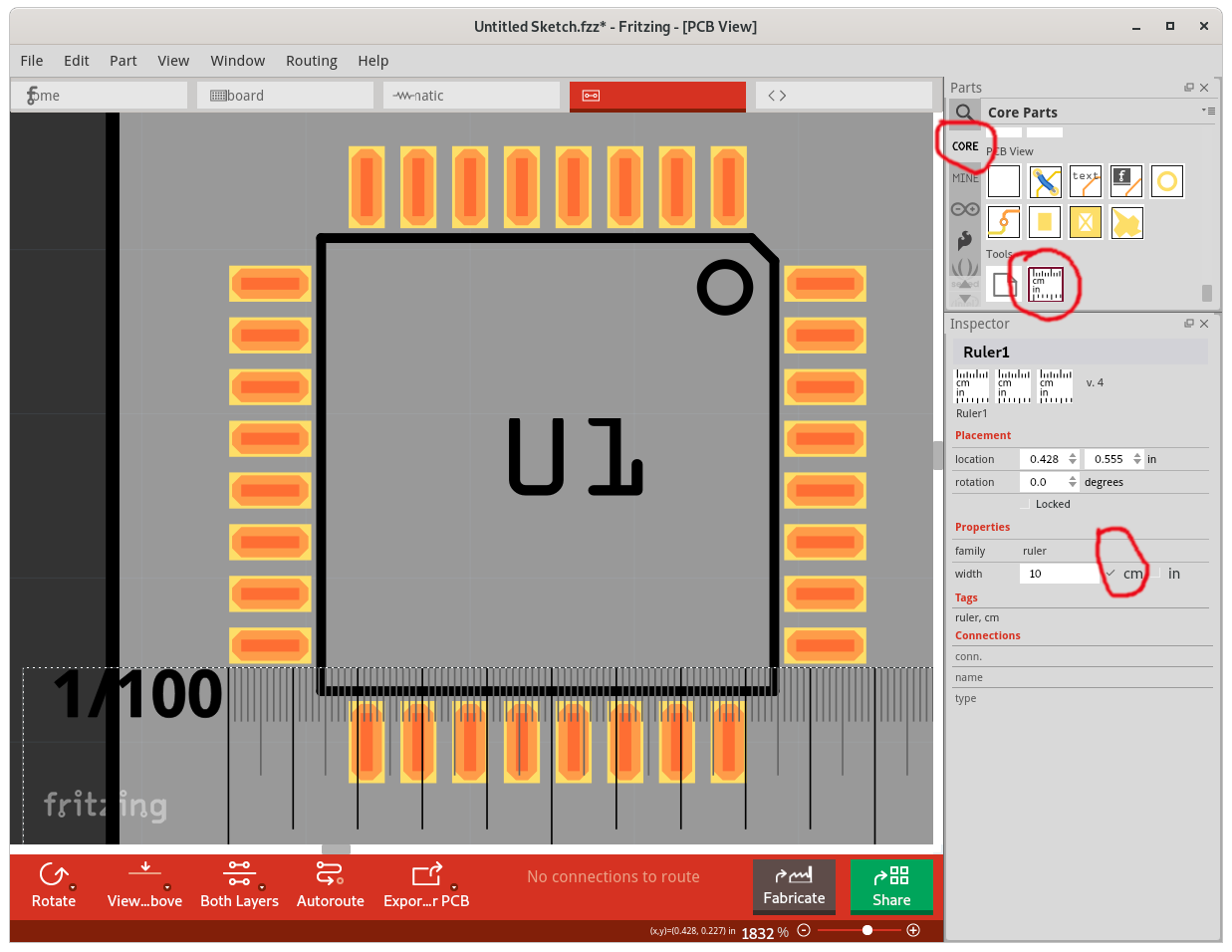
As (at least) a first approximation, you can check the footprint size of an existing part by dropping a ruler tool on the pcb view.
Hi Peter,
I am greateful for your answer, thank you.
I decided to not use the MU because it is so small (0.5x0.5), instead I am looking at atmega328p-AN (or AU, not sure what the difference is). Found add farnell.com.
Following your advise, I used the one you mentioned. But checking the footprint, the tqfp32-08 it doesn’t match. I have edited the SVG file and created a part that should match, which I will be happy to share. It is my first ever new part though.
- It is possible to exchange the one I just made for the tqfp32-08, without having to remark make schematic.
- Using the tqfp and checking the routing it keeps saying the legs connect where they are wired.
Hope you have time comment.
Best Regards
Jakob Doepping
Yes, in Parts editor you can use File->Load image for view to load your new pcb svg and then save the part (which will leave breadboard and schematic the same.) Alternately you can unzip the .fzpz file, replace the pcb svg with your new one and rezip it in to a .fzpz file without using the parts editor. If you need to replace your part in a sketch, select the part and right click and select delete minus will delete the part but leave the traces. You then drag in the new part and move the end of each trace til it connects to the new part.
I’m not sure what this is saying, can you post the sketch (the .fzz file) where this happens and I will have a look (your new part should be in the temp parts bin of the .fzz file so the part isn’t needed.) Upload is 7th icon from the left on the reply menu.
Peter
1 Like