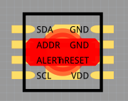
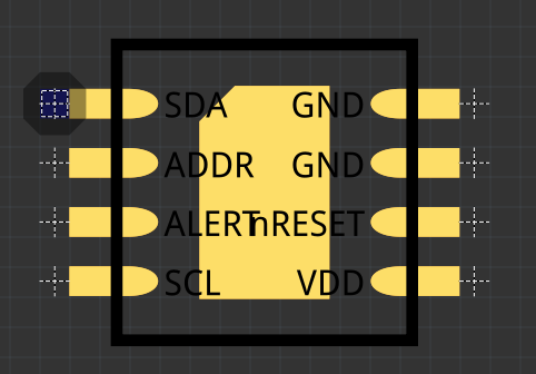
I have designed my own part, which is very small. It is a SMT precise temperature and humidity sensor SHT35 2,5x2,5 mm.
On Schematic is all O.K., but on PCB are all wires connected together to any red square, which I have not on the source graphic. I did already arount 15 own parts without problems (except beginer’s bugs), but this is my first, so small part and i see this issue first time.
I tried change connection points placing to another layers, but without effect.
I thought also, that it can be depended on set of “Trace width” or “Via size”, but change of these parameters don’t help me.
I wanted put here a short videofile, but is not possible.
Fritzing 0.9.6, Windows 7, 64 bit.