I’m running 0.9.3b on Ubuntu. When I place a Arduino Pro Mini on the breadboard it shows up, but after I close and reopen the file the Pro Mini is gone from the breadboard view, but is still in the PCB and Schematic views. If I place another Pro Mini on the breadboard, the part is duplicated in both the PCB and schematic views. Many of the holes stay green on the solderless breadboard in the Breadboard view though, like the Mini is still there but not being drawn.
I’m using the Pro Mini from the Arduino section.
This happened to me too but it is actually there and the sketch works as expected so I didn’t worry about it and kept working.
If you would post the fzz file I’ll have a try on Windows and see what happens. This may be a fault in the part, if the layer id is missing or it isn’t properly registered with the parts database I’ve had this happen (works in the first session but not when its saved).
Peter
1 Like
@vanepp Attached is the file. Thanks for taking a look.
arduino_pro_mini_problem.fzz (18.3 KB)
Well first the good news, your fzz does the same for me and the exported mini part is configured oddly which I think may be the issue, its layer name is breadboardbreadboard which is generally the special family for breadboards and may be the problem (as fritzing treats it specially) and it has some of the pins set to female which is also unusual (normal only on breadboards). However when I pulled all three of the versions that parts search found in the parts bin in to a sketch and made some connections to each in breadboard and saved it (on Win7 with .93b and the latest parts downloads) and saved and reloaded the resulting fzz it displays properly unlike yours. I’ll poke further and see if I can spot the problem. Odder yet I just discovered the third version is in fact the exported part from your fzz which appears to work fine on Win7 after being exported from parts manager. I’ll probably try recreating your entire sketch from scratch, since it is also possible this is a database corruption problem (usually caused by making changes in more than one view) and the only know way to fix that is start again unfortuntatly.
Peter
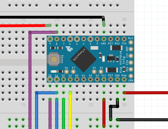
OK, I think I have figured out whats wrong. I think the problem is your positioning of the mini on the breadboard. If you do that as you have the middle pins (between the two rows on the edges) connect (unlike real life I expect) to the pins on the breadboard shorting some of the pins to each other. That likely causes database corruption and causes the part to disappear as a side effect. The solution is to move the mini down the breadboard so the pins don’t short. With the mini as originally set on the breadboard gnd is shorted to +5V via the right side middle gnd and +5V pins (which connect to the 5 pins all bussed together on the breadboard). I expect in real life there aren’t pins there and there isn’t a problem, but fritzing makes the connection if the pins are on top of each other and that likely causes the problem. To solve that I moved the mini to the end of the breadboard so the extra 6 pins hang over the bb area that has no connectors so they won’t short. I also used the power strips on the bottom to distribute power and ground although direct connections will work the same in practice. Now it appears to load and save correctly (at least for me on Windows  ). As a side issue, I think your connections to the battery charger are incorrect (I’m not sure mine are any better though, you need to look over the documentation for it ). As well I think the display may be 3.3V only and thus may need level translators to and from the 5V signals on the mini (or a 3.3.V mini and a 3.3V output battery charger) again check the documentation (Adafruit’s is usually excellent!) to see if it is 5 volt tolerant (many displays are not!). Hope this helps!
arduino_pro_mini_problem_fixed.fzz (18.2 KB)
Peter
1 Like
Awesome, thank you very much. It opens fine for me too, and I appreciate suggestions on the circuit layout. The Pro Mini I’m ordering is 3.3 volts, so I think I’m in good shape there. I’ll double check that the 3.3 pinout matches the Fritzing part though.
This was all very helpful. Thanks again.
There is a pro mini 3.3V Fritzing part available if you enter the search term arduino pro mini in parts search (it may be in Sparkfun somewhere as I don’t see it in Ardunino but it does come up in search). You likely need to see if the 3.3V mini will take 5V as its raw voltage or the lipo charger/regulator comes in a 3.3V version though. Doing without level translation is a good bet as translation is generally a pain.
Peter
I swapped the Mini that was there out for the 3.3V Mini from the search. However, the schematic view doesn’t show any connections to the Pro Mini now. I’ve even tried to replace a few wires with no luck. Am I missing a step?
I guess I should add that if I connect the wire directly to the Pro Mini’s thru holes the schematic is fine.
It seems that both of the other Pro Mini parts have that problem. If I put in the “Arduino Pro Mini V13” part everything works fine.
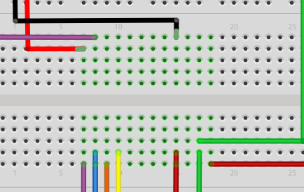
From the picture (with no green dots on the breadboard connections) it looks like the mini hasn’t aligned with the breadboard correctly. You could try moving the part with the mouse a bit and see if it suddenly connects (there is a bug that sometimes parts come up misaligned to the grid). I’ll have a poke at it in a bit and see if I can reproduce it.
Peter
I an reproduce this on one of the sparkfun pro minis (the 5v one). When dragged to breadboard with grid size set at .1 in doesn’t (and won’t even if moved) align to the breadboard and connect. A work around is in View->Set grid size change the grid size from .1 to .01 and you can then drag the mini part til the connectors turn green (which indicates a connection to the breadboard). I should have pointed out in the post above that if you click on one of the mini connectors it should light up yellow. If the alignment to the breadboard is correct, the five breadboard connectors should also light up yellow (which I’d guess won’t happen in your original). When the grid size is set to .01 and the mini snaps to the grid the mini pins go from red to green to indicate they have connected to the breadboard pins, and then the entire row goes yellow when clicked on. It looks to me as if the core parts may be not quite correctly aligned. I’ll have a poke at that in a bit.
Peter
1 Like
As is often the case, I was wrong. All the parts will work on a breadboard because the vertical pins are set to female (the version 14 5V and 3.3V minis have all the pins set to female which is why they don’t work on the breadboard). You do have to change the grid size from the default .1 to either .05 or .01 to be able to get the pins to align to the breadboard but once that is done these two new mini parts (changed to version 15) will work on a breadboard the same as the v13 part as long as the grid size is changed and the part is dragged til the pins turn from red to green (to indicate they have connected to the breadboard). The pins in the middle and end of the board can still be connected to via wires, but they won’t connect to the underlying breadboard unless you place a wire from the pin to a row on the breadboard.
Arduino Pro Mini (3.3V) fixed.fzpz (25.1 KB)
Arduino Pro Mini (5V) fixed.fzpz (25.1 KB)
Using these new parts should make your sketch work.
Peter
1 Like
I tried the new 3.3V part and it works great.
Thank you for your help on this. As a newer Fritzing user I was having a hard time figuring the problem out.