Arduino Nano I/O Shiled

Hi,
While I was using fritzing platform, I noticed that the Arduino Nano V3.0 I/O Expansion Adapter Board Shield doesn’t exist. The fact is that I need this board shield in order to construct a diagram for my circuit. Is there anyway to find a .fzp file for this board shield?
Thank you very much.

I don’t see one anywhere, but there appear to be several varieties of them around (with different pin layouts). If you post a link to a picture (preferably a mechanical drawing, although there may not be one) I’ll have a look at it.

Peter

Ummm been busy with my new job and haven’t checked these forums in a while but this Arduino Board can be done if someone provides a good image or some Eagle Schematic to try it with Eagle2Fritzing :smiley:

Hi,

I am new to fritzing, I am in fact also need this expansion shield part for my Nano projects, but not sure how to make one from image into fzpz part. Here is an image of it I made using illustrator 6 from some time ago. Any help to convert this into usable fzpz will be very much appreciated!

Here is a part for this. It has no pcb view as it isn’t useful, and can (with some issues) take the nano dragged over the nano on to the nano pins and it will connect. It looks like this:

bb:

Two issues here, the stock nano is the same color as the shield so the edge of the nano is washed out. As well at the bottom of the screen it is complaining about unrouted nets that aren’t really there. Schematic is also somewhat ugly as the stock nano is not particularly compatible with this shield. That could be corrected with a different variant of the part, if someone wants to make one.

Here is the part:

Nano-V3.0-IO-Expansion-Adapter-Board-Shield.fzpz (27.8 KB)

and the test sketch above:

test Sketch.fzz (74.5 KB)

Peter

1 Like

The part is well fit in version 0.9.3b. Here is my example that I find it pretty neat.

Arduino Nano IO Expansion Board Example.fzz (129.9 KB)

I have been looking for this part over the internet since many months ago but no luck, so I decided to use whatever part related in the core parts and recreate the image.

Anyway, thank you very much for the kind effort!

Henry

Something ugly has happened to your .fzz file. It is not rendering correctly for some reason:

The shield board is missing completely (although showing in schematic). The power plug has been replaced with the IRF520 module, and the icons in temp are wrong. Did you edit the .fzz file by chance? I’ve never seen a sketch like this before … I’ll have a look at the .fzz file and see if I can tell what went wrong. On an unrelated style issue, I would normally do the connections like this (on the fc-51):

so that it is obvious that there are three wires in the bundle at a glance and where they connect to. Either way will work, but I prefer the connections be obvious at a glance.

Peter

Owh, its weird that the parts are scrambled all over the sketch, same goes when I reopen my fzz.

Henry

Well my first fear is unfounded :slight_smile: , I was wondering if the no pcb in the Nano shield was having an unexpected effect, but it doesn’t appear so. It looks like something on your system corrupted the fzz file when it was written. I recreated the sketch and it appears to load fine now:

Several things to note here: the red circle around the fc-51 is how I would route the wires to make the connections clearer. To do this I clicked View->Set grid size and reduced the grid size from the default .1in to 0.05in:

Capture5

to allow closer spacing of the wires. The vertical layout of the nano shield makes the breakout more difficult, but with the 0.05in spacing you should be able to have at least a stub on the servo connector which shows where the wire terminates. The other thing of note is I have less parts in the mine parts bin (the red cirle on the right top.) That is because the barrel connector and the fc-51 are both now in core parts. You probably need to click Help->Check for updates to update the parts repository to the current version. In any case here is the .fzz file which now loads correctly for me:

test.fzz (82.4 KB)

Peter

Thanks for the tips on how to set the grid size so I can make the wires look more organized, and I wouldn’t know it can be updated until you told me to. Updated for now.

The test sketch you provided can be loaded at my side without problem.

Many thanks!

Henry

Hi All,
I have a question about the part. I create open source eductional stuff based on a robot that uses this board (https://wikifactory.com/@willemluijkx/mojo-dojo, https://www.thingiverse.com/thing:4210910)
I started using this item for creating instruction schematics. Are you guys the creator of this component, if so, is it okay if I use it like this? I’ll credit you where I can.
Kind regards,
Willem

In general all the parts are (I believe anyway) licensed under the Creative commons license. In this particular case I am the author of the part and you are free to use it for whatever you like. Making Fritzing parts is a fairly complex process (it took me a couple of years and a lot of help from here to learn to do it) so if you need changes or parts that don’t exist yet, feel free to ask. One late issue I will point out, is that while Fritzing is open source and you are free to build it from source (which is quite difficult), in order to support the forum, websites and development, there is now a pay wall (which is causing a lot of concern) for the download of Fritzing. Unfortunately the old way of free downloads of the distribution with a request for donations resulted in something like a 0.01% donation rate and Fritzing was dying. I prefer the old method of free download, but I would also like to see Fritzing survive and 3 unsuccessful years trying to restart development has convinced me this is the only way to insure that (although an alternate way would be welcome if you know of one!)

Peter

1 Like

Hi Peter, thanks for your reply. I thought so but I did not find anything on licencing of specific parts, thats why I asked.
Since Fritzing is now my schematic tooling of choice, I’ll certainly donate. And since I’m a big believer in open source (I always try to teach kids about open source when I’m teaching), I’ll support Fritzing where ever I can.
Willem

Hello, thanks for this parts, It’s really helpfull…

I edited it to fix those two issue…
Just recolor the pcb, & for the schematic issue, I use “breadboard” family…
So, It’s now only has bb view …

See, if this is correct…
I edited pin as the one I have…
117. Nano Expansion Adapter Shield (AG).fzpz (18.2 KB)

(I make the NC pin to 3V3 as UNO)
IMG_20200424_023024

Sorry the shield is still out of scale… It does not fit as uno…

Capture1 Capture2

Most of the pins not aligned correctly…
It doesn’t matter for the extended breakout pins,
But, I corrected to the Uno pin, holes (ref - Uno breadboard)

117. Nano Expansion Adapter Shield (AG).fzpz (18.8 KB)

This is likely why it would be a good bet to figure out (assuming it is possible, which I expect it is) to configure Illustrator to use in or mm as the drawing units. Your breadboard svg is dimensioned in px which is likely what is causing the scaling issue (this is from your original post’s breadboard svg):

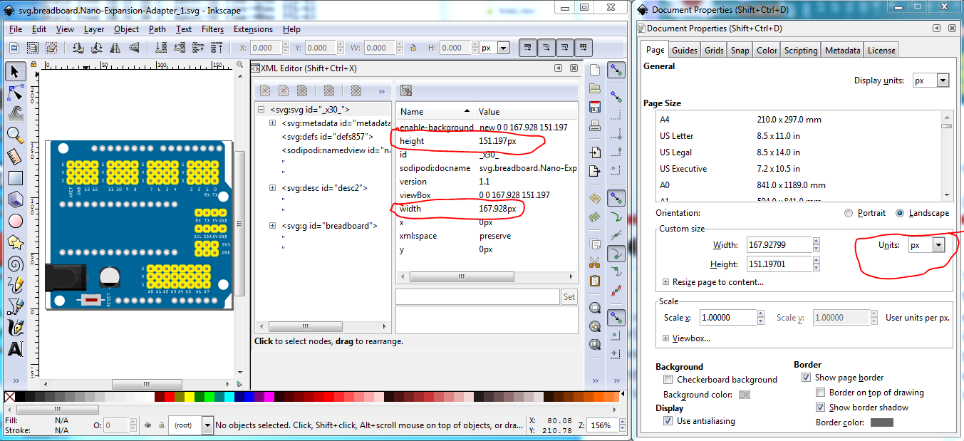
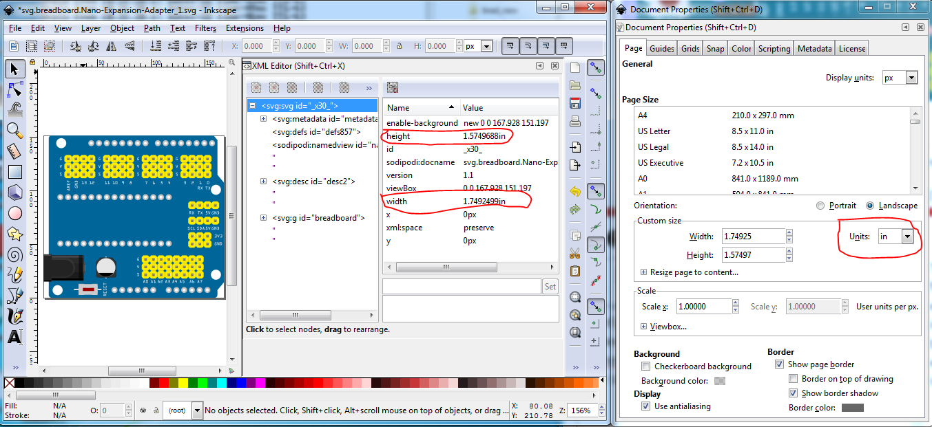
Units (in Inkscape not Illustrator!) are px, which makes the document height and width in px. Converting that to inches in Inkscape doesn’t do anything about the scale (without a rescale) but does change the document sizes to use inches where the px the editor uses doesn’t matter because an inch is an inch.

I haven’t been able to find anything useful in a google search for “illustrator set document height and width” although I’m not sure that is what I really want to do here :-), this may help it indicates there is (sometimes) a height and width box on an artboard (note I don’t know what an artboard is :slight_smile: ), and that might set the metadata for the svg in to in or mm if set that way.

As well, I’m not sure why you suppressed schematic. There isn’t anything wrong with schematic, it works fine. What is needed is a different variant of the nano which has a schematic with all the pins on the right side (as I did with the uno in this post:

the reason I didn’t do this for the nano is there is a bug that currently makes this not work correctly. Once we get that bug fixed I intend on making shield friendly schematic options for all processor parts.

Peter