in the documentation tab. Unfortunately while the breadboard image is a work of art, the part lacks pcb (the svg file is 0 length and causes a load error in Fritizing) and is internally a mess (a bunch of unused bus connections, bad pin numbering etc.) Here is a corrected part with those problems fixed and connections for the battery connector added in breadboard and schematic (they are terminal blocks so can’t connect in pcb). While I think this is correct I don’t have a board to check it against so if someone that does would check it that would be appreciated. I changed schematic fairly radically. It is much smaller, on .1in centers rather than .4in, and with the pin out matching that in breadboard which I prefer to the usual Arduino part layout. If someone doesn’t like this, I can produce a schematic svg in the usual format. Due to the number of changes I made this as a new part rather than a modification of the original. To the Arduino folks: if you wish to put this part on your store page, please feel free to do so (in fact please do so, the one that is there is broken ).
Probably not, this one is hosted on the Arduino site, not in core. The breadboard is a work of art, but it is huge. I was to lazy to replace the art with small but good enough …
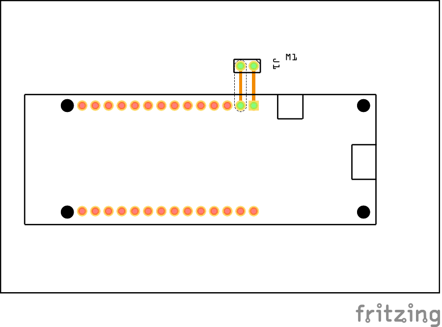
Not sure if this is of any use. I took the breadboard image and tried to reduce image size by removing vias and traces etc. I ran out of energy trying to clean up pin numbering etc.
By all means upload it. I thought about doing it, but it is a lot of work as was the original. If I was going to submit it to core parts I would replace breadboard completely with a much simpler version. At some point after I get a development environment running (i.e. maybe a long time from now ), I’d like to stick some timing code in the render engine. I think that large files and especially transforms (because of the matrix multiply that they require) are a performance problem. But other than gut feel I have no proof that we should be seeking to minimize them. This particular part is hosted on the Arduino store site so I left breadboard as is to make a better chance that they would use my vesion (which loads correctly unlike their current one).
Hi there, thanks for the nice design. However is there any chance you have switched the top and the bottom for some reason. I see it the way it should be on the Breadboard view, but when I go to the PCB view it seems like the headers are reversed. Is it just me being a noob or this is indeed the case?
Thanks!
It isn’t my design (I’n not that good ) but someone at Arduino’s design. However the part on their site is broken (the pcb view svg is 0 length) so I fixed it for someone. That said it doesn’t appear to be wrong, it is reversed for what ever reason in pcb when I just loaded it, you need to rotate it 180 degrees to match breadboard (that may be an artifact of where I cloned the pcb svg from):
To correct pcb view just right click the board and select rotate->180 degrees and then they will be the same direction. I just looked and the pcb svg is oriented the correct direction, so either there is a flip modifier in the fzp that I didn’t notice or the loader is flipping it for some reason of its own.
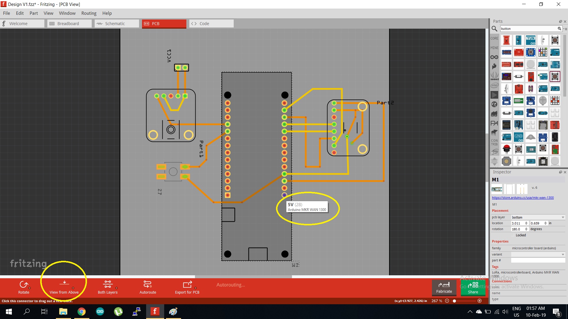
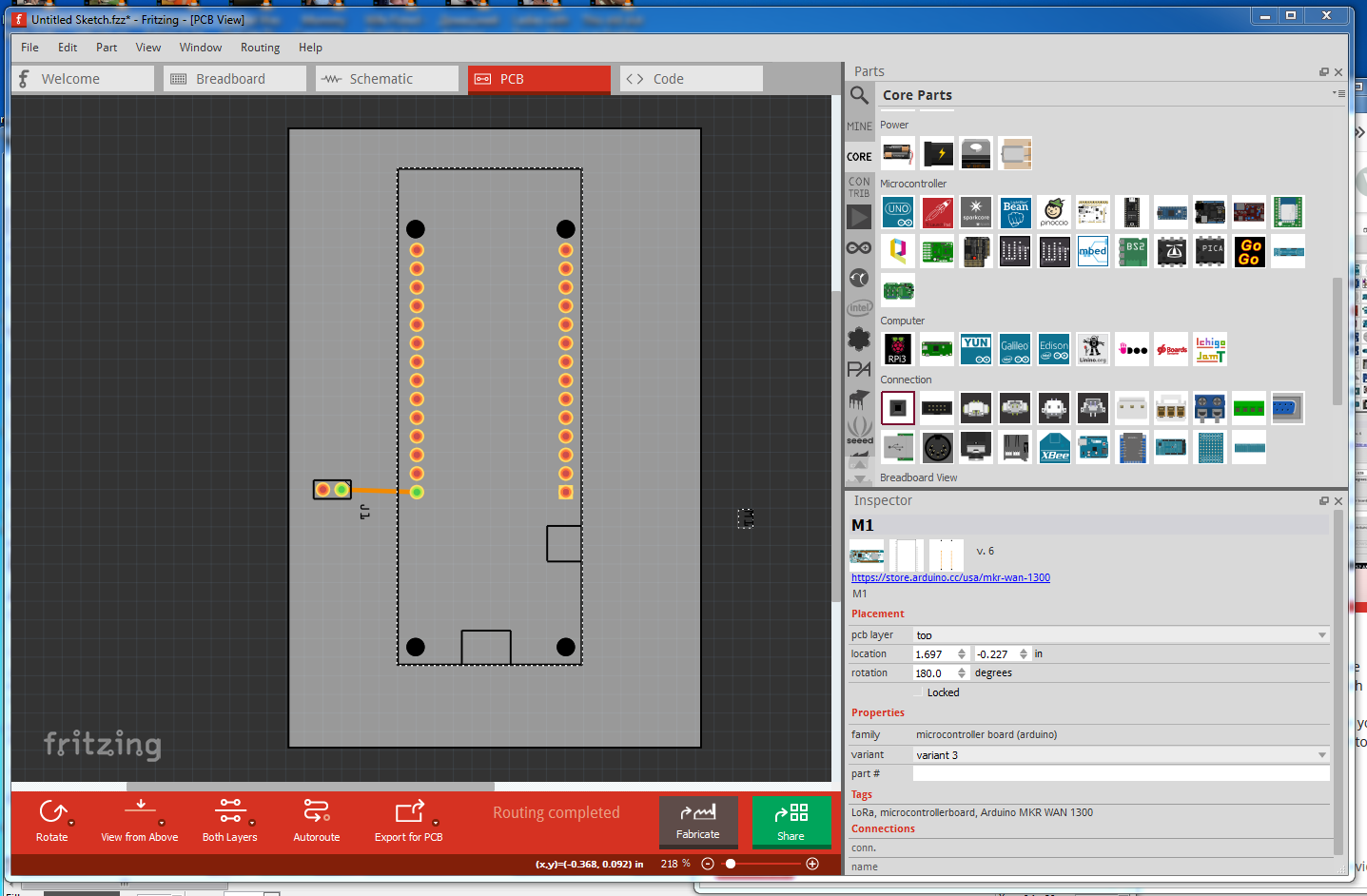
Ah! yes appears to be a newby mistake. You have placed the part on the bottom of the board which will indeed make the part appear incorrect. In inspector (the bottom right window) under layer you see the layer is set to bottom. By defautl it is set to top and the layout appears correctly:
It may not have been your fault, Inspector tends to change things you don’t intend when you change something you do intend. I think it is a quirk of Qt (the graphics framework underlying Fritzing).
 ).
). ), I’d like to stick some timing code in the render engine. I think that large files and especially transforms (because of the matrix multiply that they require) are a performance problem. But other than gut feel I have no proof that we should be seeking to minimize them. This particular part is hosted on the Arduino store site so I left breadboard as is to make a better chance that they would use my vesion (which loads correctly unlike their current one).