Arducam Mega 3MP SPI OV5642.fzpz (5.9 KB)
I made a Fritzing part for the ArduCam Mega 3MP.
Part can be found here
Hi, the part seems to have some scaling issues.
For example, the connector doesn’t align with typical standards.
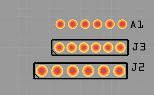
The pin spacing seems to be slightly bigger than 2mm , about 2.1mm.
Most common is 2.54mm, and this is also what the breadboard uses.
See how it compares to a 2mm and a 100mil (2.54mm) spaced connector:
Both the schematic and breadboard view suffer from similar scaling issues.
OK here is a corrected version of this part (with some changes which may be undesired!) that correct the reported problems with an explanation of why they were done. First an explanation of your scaling issue (I am assuming you are using Inkscape which you appear to be, if not this may be more difficult as other svg editors appear to have less control of the image.) The problem is that you are using px in the dimensions when it needs to be in inches. If it is px Fritzing will guess using either 72DPI (Illustrator) or 90DPI (Inkscape versions around 0.9.2.) Current Inkscape (which we both appear to be using) use 96DPI and the scale is thus off. Inches do not change with DPI and will thus render correctly no matter the DPI in use. To change this select File→document properties and change px to in. In addition there is no layerId (which in this case should be breadboard to match the .fzp file.) Without that the part will not render as an exported image (that is the only consequence I am aware of, but it will cause complaints later!)

The documentation indicates the camera should be 34.5mm square as indicated here:

Here are the problems in breadboard: The dimensions are px they need to be in inches (or mm, but inches are easier.) To change it copy the largest px dimension (maximum resolution) value (111.809 in this case) to the clip board then change the scale to 0.001.

The scale wants to be 1/1000 in (scale of 0.001 with the dimensions in in) to meet the graphics standards and the entire svg needs to be a group with the name “breadboard” so now paste the 111.809 copied above to correct the scale.

The scale wants to be 1/1000 in (scale of 0.001 with the dimensions in in) to meet the graphics standards and the entire svg needs to be a group with the name “breadboard”

This has also set a viewbox value in the svg header which is required by Fritzing (as a side effect of setting the scale which needs the viewboz) which was missing in your original svg. Here we see the camera (with the header which wanted to be 0.1in removed to be replaced with a more suitable connector) is the incorrect size, only 25.908mm instead of the 34.5mm specified in the documentation. To correct that select the entire camera element (without the connector) and change the width (with height locked to width) to 34.5mm to correct the size.

I then deleted the style and xml; space = preserve attributes as unneeded (the xml: space attribute bothers lxml which FritzingCheckPart uses.)

Then I copied in a 6 pin 2mm grove connector and rescaled it to be 0.1in pitch instead of 2mm as it more closely matches the real connector on the edge of the camera. I changed the pin numbers to be connector0pin to connector5pin and moved them to the bottom of the svg (because I have tools which will renumber them if I need to if they are the last thing in the svg.)

With that done (and the camera body moved up so it overlaps the bottom of the connector which was then centered in the camera body I did an Edit→Select all and then Edit→Resize page to selection to set the size and viewbox correctly, then an Object→group to create a group of the entire svg and set the group id to breadboard like this.

Then I select File→Save as and select the type to be plain svg

Then hit Save and then click replace to replace the svg file without all the Inkscape specific fields which sometimes break Fritzing. You should do this with all Inkscape svgs for use with Fritzing to avoid problems.

For schematic I used Randy’s Inkscape extension (covered in the tutorial) to create a new schematic which will match the graphics standards and used the following connector diagram from the camera documentation to set the pin names. I see an indication in the fzp file that says pins reversed which may mean this is incorrect for some reason, but a standard Fritzing part should match the manufacturer’s documentation which appears to be this rather than the order in your part which looks to be the reverse.

This part has VCC on the left as the camera appears to have (which may not be what you want for some reason.) For pcb (which is the wrong size) I replaced it with a 6 pin 0.1in header pcb which will presumably connect to the camera via wires (and can be reversed there if needed for some reason.) I then the .fzp file and the svgs through FritzingCheckPart.py to remove the px from the font size and check that that part is correct, then loaded the part in to Fritzing and checked the part loads and connects correctly and exports correctly as gerber files which leaves this part which should do what you want I think. If you have questions or don’t understand something feel free to ask.
Arducam Mega 3MP SPI OV5642.fzpz (5.5 KB)
This part has a new moduleId so it should load along side your current part so you can compare the two.
Peter
1 Like