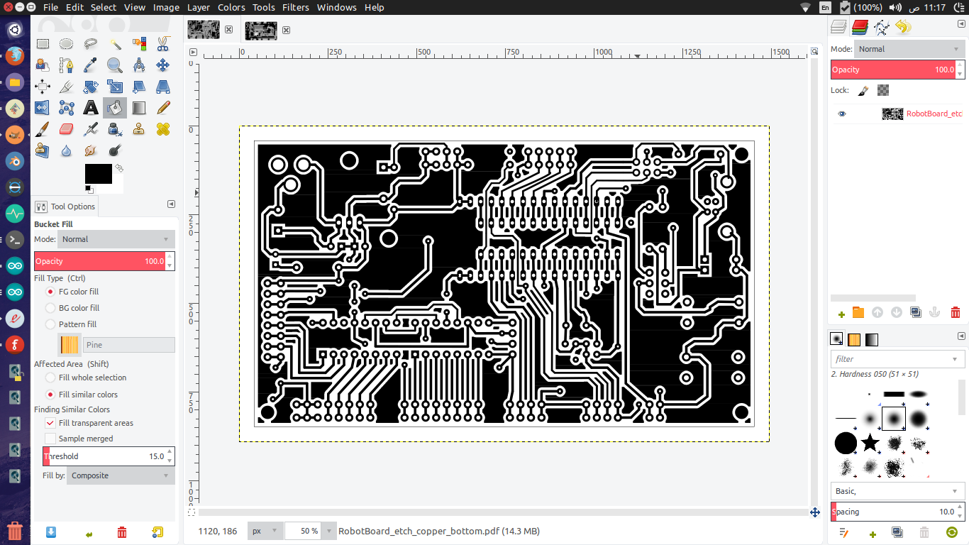
I dont really need to explain just look at the picture ( open it ), this happens with almost all of my boards whenever i export a pdf. Since im home etching i can just open gimp and paint them one by one using the bucket tool, but its an just an extra annoying step when dealing with a complex double sided PCBs
there has been older discussions about it before
Im using 0.92
It looks like they couldn’t track down the problem so they didnt much care about it since it doesn’t effect the circuit ( traces ) and it also doesnt effect the board when ordering it ( at least according to replies from old forum discussions )
but it certainly does effect my home toner transfer so i have to some how get rid of them
In the Gerber it looks ok, so you can export for production the Gerbers and get a Gerber program to display it, I use KiCad GerbView, and then print off that.
There is an online Gerbviewer, but I don’t know how that works.
I just remembered that Gerber doesn’t have the drill hole in the centre, and that means that the drill guide spot is missing from the centre making it hard to locate the drill unless you put a centrepunch in the centre first.
Sorry, but don’t worry about these! They are just rendering artefacts and won’t affect your print or production. The copper fill is created with a scanline algorithm, so it’s basically hundreds of black rectangles stacked vertically. There is no gap between them, though, but the PDF viewer sometimes displays them as 1px white/grey lines.
I admit it’s confusing… There’s a patch from Nicolas Raynaud to replace the scanline algorithm with a proper boolean-based area merging, but it’s not quite there yet: https://github.com/fritzing/fritzing-app/pull/3083
Anyway, as I said, it should not influence your etching process.
My first suggestion is to upgrade to 0.9.4 (released about a month ago), the fix may or may not have made it in to there. If it still occurs then you need to report it as a bug on github here:
as a bug because it won’t be tracked (and may not be noticed) here in the forums. From a quick look, this fix may have made it in to the 0.9.4 release or it may not, as it appears to have perhaps have been merged as part of the major gerber rewrite which got backed out about 2 years ago (as parts of it were broken.) Unfortunately the folks who did that commit appear to have given up on Fritzing possibly because development and releases had died, and did not respond to requests for help to fix the code, so it got backed out. Development is trying to restart so there is some hope that this may get fixed if it is reported. It is possible this specific fix can be integrated independently of the larger fix (since it looked to be separate) if reported.
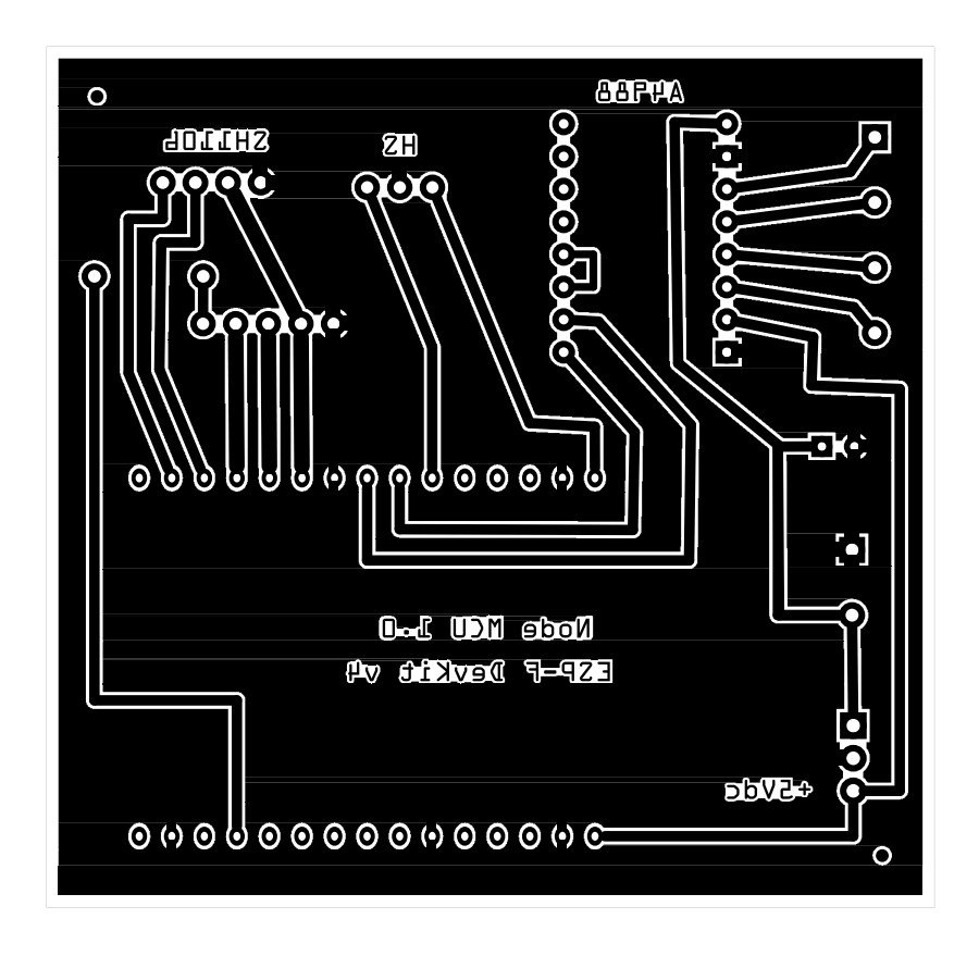
Thank you for your suggestion which I tried. The problem still exists in 0.9.4 as demonstrated in the attached files where the ground integrity is compromised by the extraneous horizontal lines.
That would indicate as I suspected that the fix got backed out as part of the gerber changes. If you are lucky the fix may be able to be applied standalone without the rest of the gerber changes as it looks to have originally been standalone and got integrated in to the larger gerber fix. Refer to pull request 3083 (which is closed) in your pr as a source of a fix. Development is only just restarting so it may be some time before anything happens. I don’t know of a time line for the 0.9.5 release yet.
As a workaround you can export the PCB to SVG and import it into Inkscape. You will still see the lines in InkScape, however not on the print.
This also allows you to print multiple design’s on a single sheet ( i use UV light method for creating PCB’s)
I once created a boring video which demostrates how to do this:
It may be possible (if ugly) to use Inkscape to edit out the lines. Alternately you can export the sketch as gerber and perhaps get what you need from the output of a gerber viewer such as gerbv (as I recall this is a svg/pdf issue and gerber output is correct.) Otherwise you would have to wait til the bug is fixed and a new release.
Thanks, I have used both inkscape and a pdf editor which works but both are pain staking and time consuming but do work while I wait for an update. The gerber files are fine, I have used a CNC to successfully cut some very simple pcbs,