As always google is your friend (and Adafruit often, as in this case, has parts in their Fritzing repo.) Found via a google search of the form “fritzing part RFM69HCW”
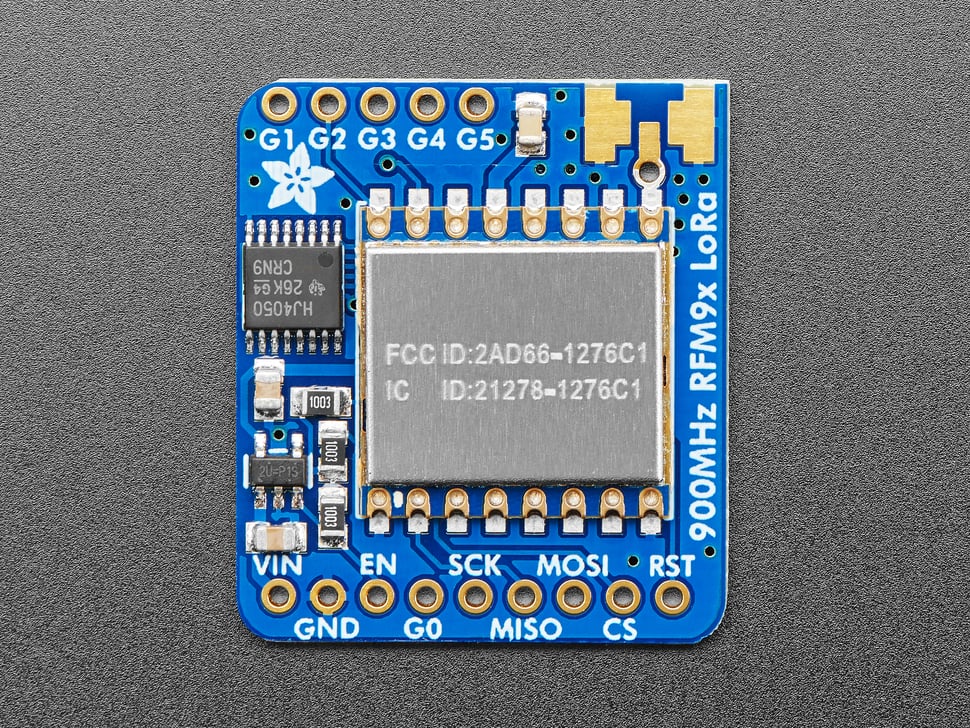
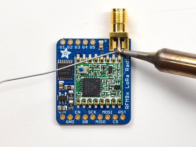
Hi Peter, thanks for your finding, but it is just a part for the whole RFM95 board for the whole Adafruit board (and without the antenna footprint in the PCB view):
I thought it could be a good idea to have the antenna print only for your own RFM9x or SIM or any other radio that uses different antenna types optional.
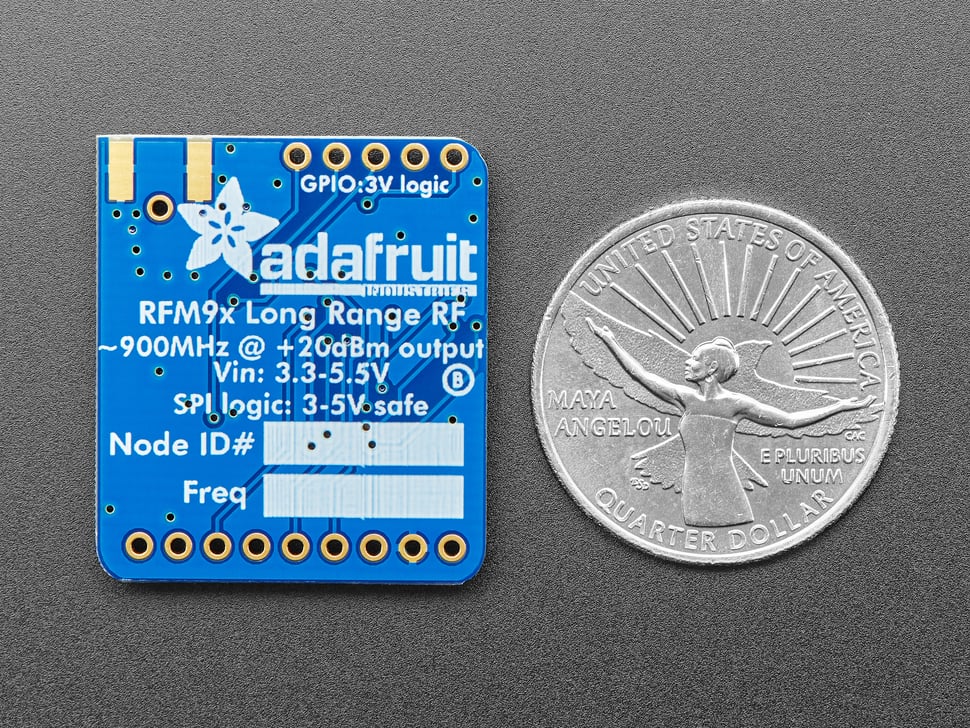
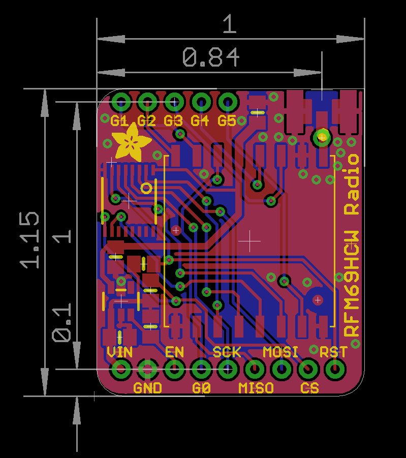
In the meantime I found also a scale drawing on the Adafruit page (just front):
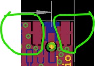
That may not be as easy as you think. It appears the ground legs are tied in to the ground plane (note the connections to the surrounding ground plane circled in green here.)
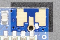
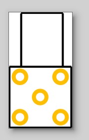
while it is relatively simple to make a footprint that looks like this it is non standard (as it combines through hole and SMD in the same part) I suppose you could make a through hole version with the same pads on each side of the board and connected together by vias which would look much like this (on both sides of the board) and with holes (represented by blue dots in this image)
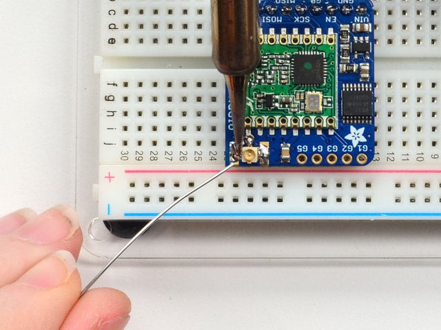
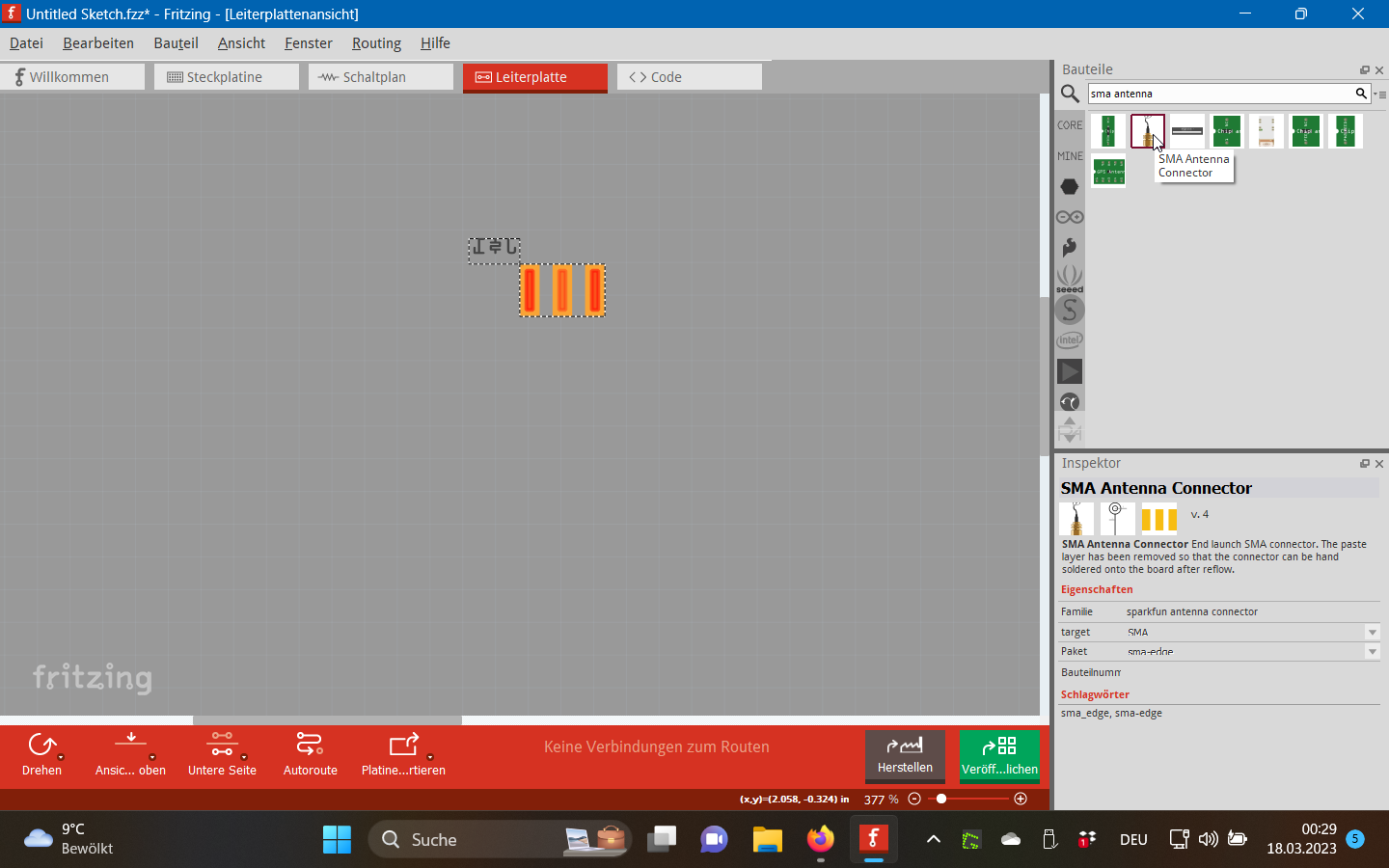
I have already made an sma right angle part for someone that looks like this
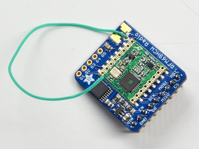
(there is also an upright version) both of which are posted in the forum somewhere. I expect it will already do what you want in a slightly different way. As I recall (without looking!) the pad in the middle is the signal and the other 4 are grounds and bused together. Connecting a wire to the center pad does for the wire antenna and the SMA connector fits in the holes. In this case one of the 4 ground pads serves as the ground fill seed.
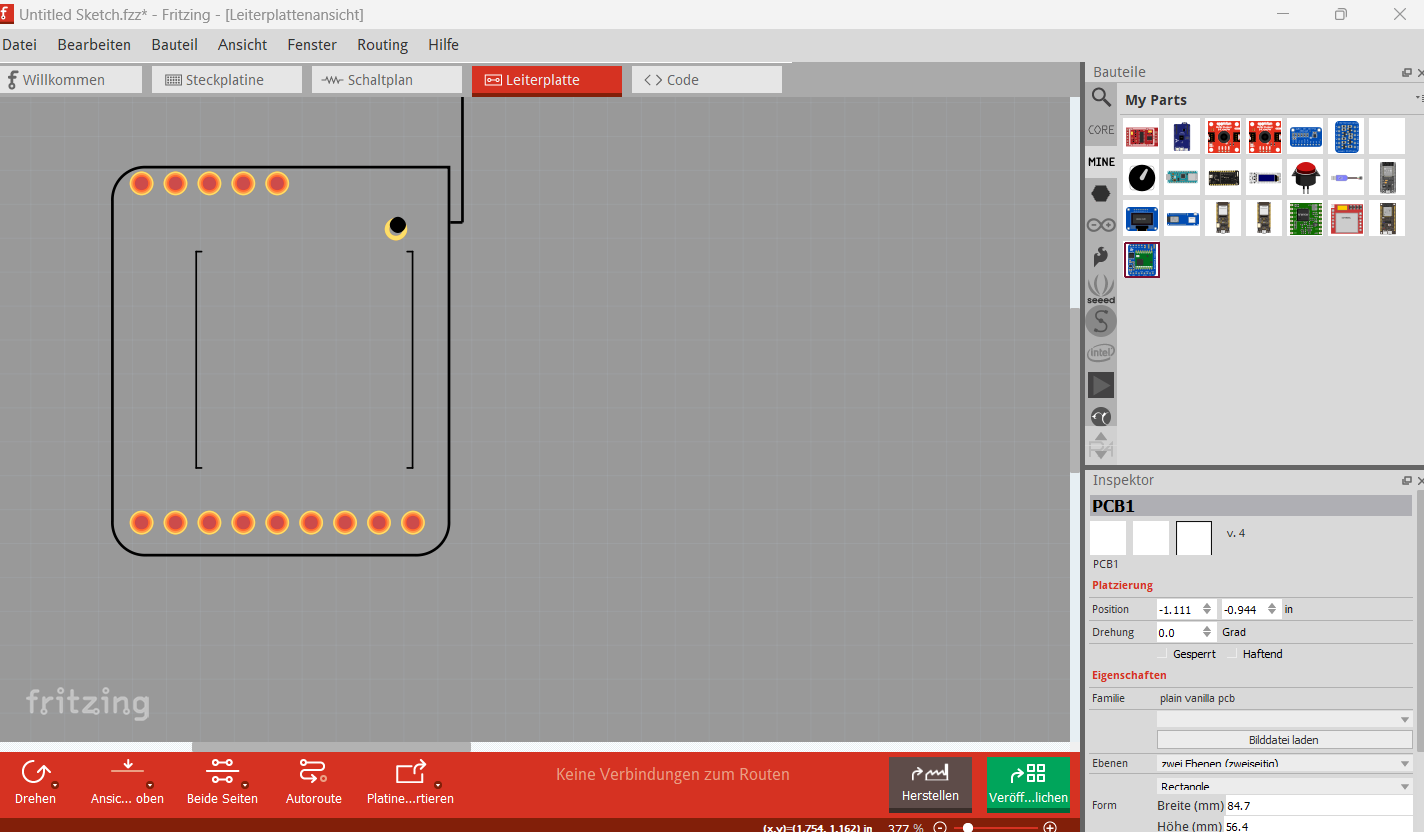
That is likely why the extra pads on the top to take a uFL SMD part. As noted it is easy enough to make a part like this if you want one. Just basically copy the outline of the Adafruit footprint with some additional holes to make the part plated through for Fritzing (which will happily make connections to either side of the board as the part is THT rather than SMD. The part will look like the middle image (the blue square) above. Do you want such a part?
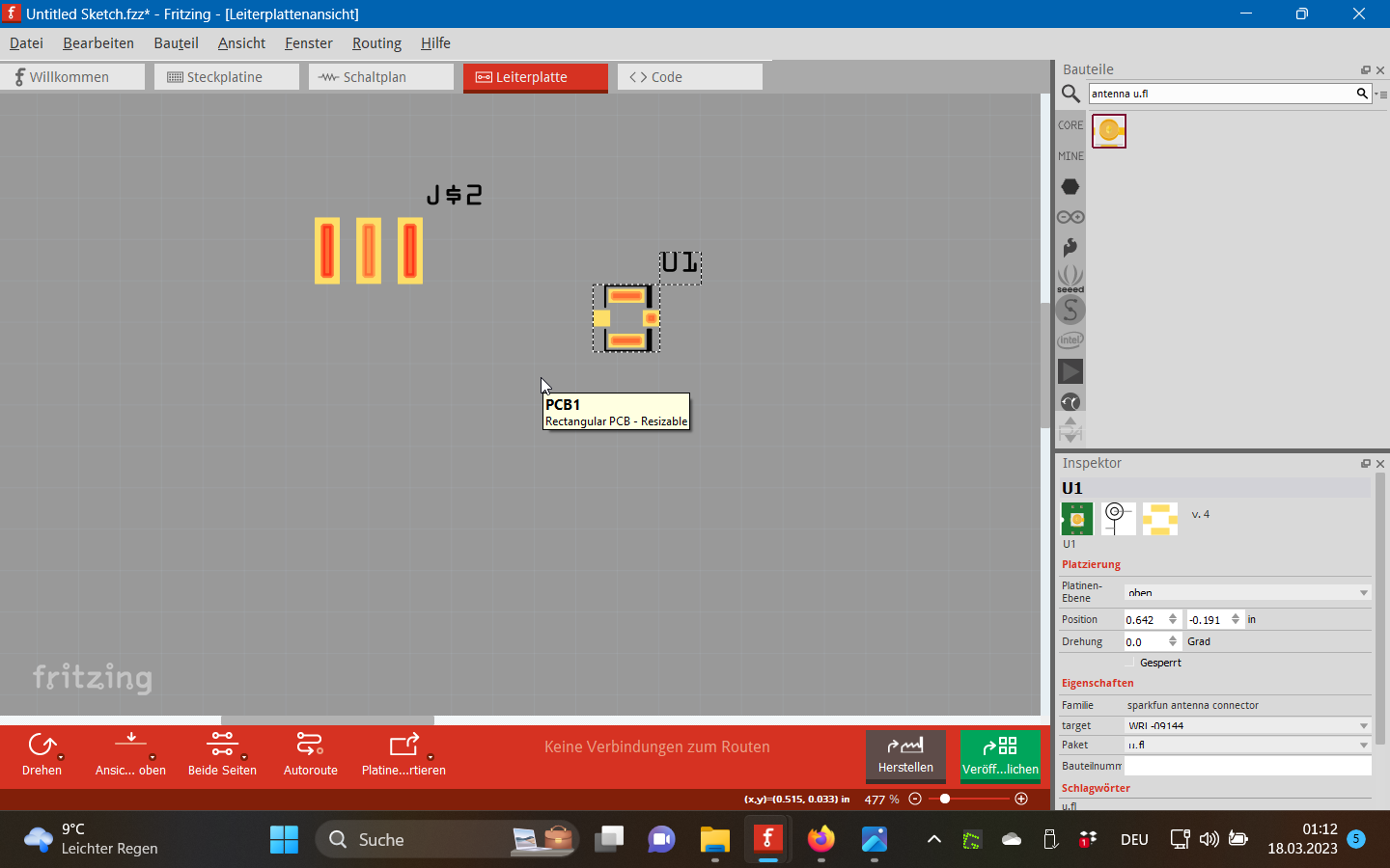
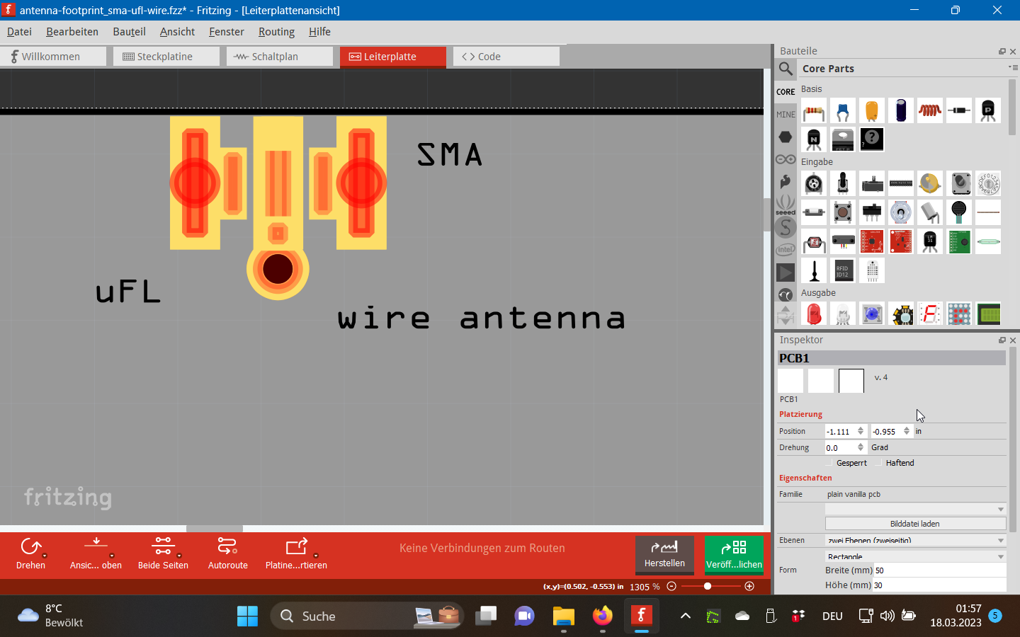
Many thanks Peter, I think I got it done, not a real Fritzing part but working for me, it is a combination of the already existing SMA footprint, the uFL footprint and a bigger via: