Do I assume white/black dotted lines are the width of the track ?
Any ideas what the green, blue, and purple dotted lines mean?
What does the different solder holes coloured green and red mean?
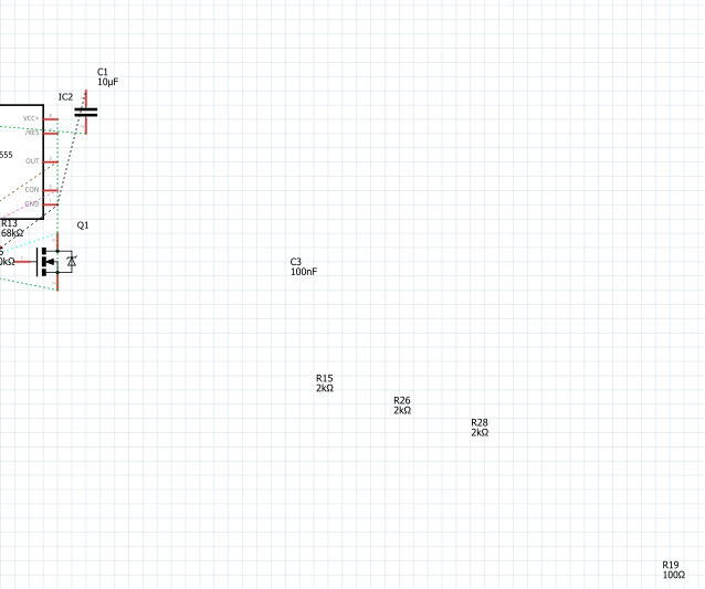
The colored dotted lines are virtual wires. They indicated that the connection was made in the schematic view or the breadboard view, but not yet in your current view (the PCB in this case) The color is random, to make them easier to track visually.
You still need to route them for a complete PCB. You can adjust them with the mouse to turn them into real traces.
Green dots mark connectors that seem ok. Red dots mark connectors that are not yet connected properly, like, only with a virtual wire.