Hi everyone, I just completed my first project on Fritzing and I wanted to have someone else’s opinion before sending the schematics to a manufacturer.
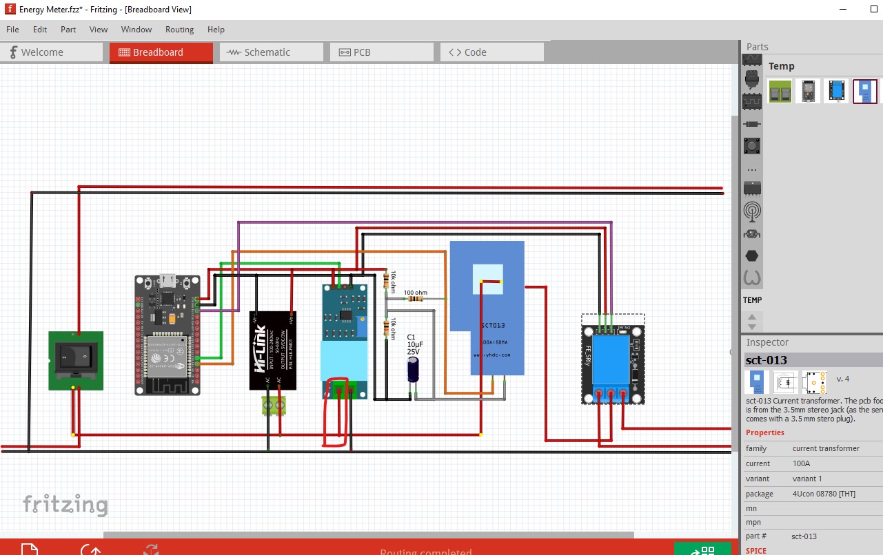
My project is an energy meter with an esp32 microcontroler, a ZMPT101B for measuring the tension, a sct013 for measuring the current and an Hi-link module to provide power to the esp32. I placed a switch at the beginning of my circuit if I want to bypass it for any reason. Finally at the end of my circuit I placed a relay so I can control a load.
I assembled everything on a breadboard and got it working, so now I would like a clean and more permanent finish but before that, I wonder :
- Is my schematic correct ?
- Are the widths of the tracks wide enough ?
- I would like to place a female jack so I can plug the sct013 instead of cutting it and soldering it to the circuit.
- If someone can think of a better layout it would be awesome.
- What pcb service do you recommend for Europe (France) ?
I hope my asks are not too trivial, thanks in advance guys.
Energy Meter.fzz (114.6 KB)
I’m a firm believer in the only stupid question is the one you don’t ask. If you don’t know either asking google (which won’t work in this case) or someone who may know are the only ways to go about it. That said you have some problems.
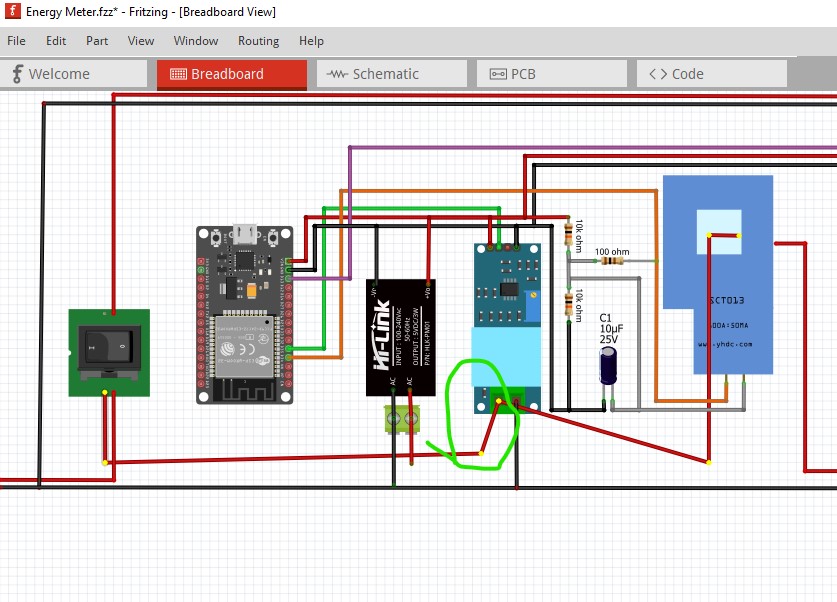
Here I clicked on one of the pins on the switch on the left. That should light up yellow everything that is connected to it. However as you see from the red circle the connection to the ZMPT101B isn’t connected (because you can’t connect to wires in breadboard I don’t think only to pins)
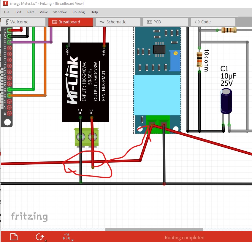
Here I dragged the bend point to the connector and it connects (I didn’t reroute the wires to make it look like the original yet though.) Now they mostly connect. I think there may be a problem with the current transformer part which is the next thing I will look at. I see I missed another connection as well
You need to drag the end of the wire to the pin on the ZMPT101B to get it to connect.
Peter
Thanks a lot for taking the time Peter. I think my mistake is that I duplicated the wires instead of bending them . For my defense those wires are for illustration purposes only since they represent the main wires  .
.
Thanks for the tip about lighting up the connection, didnt’t know about that.
Slimane
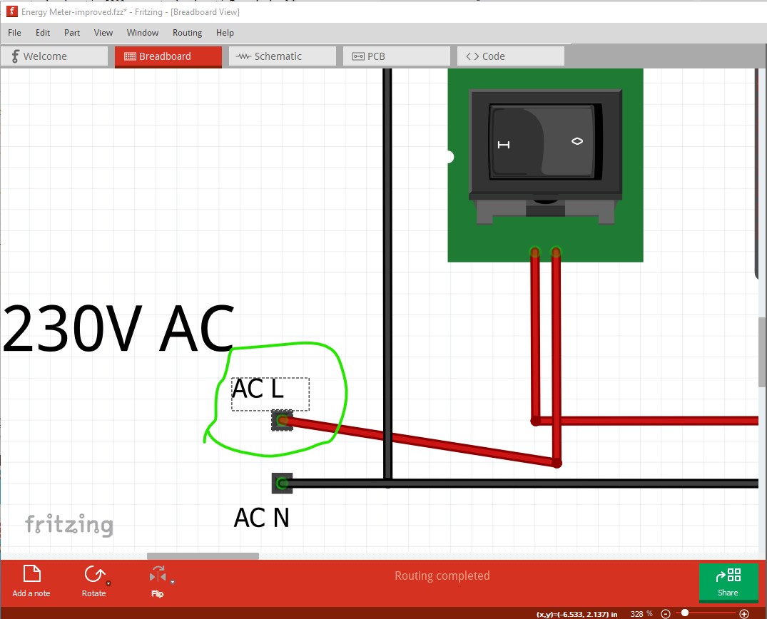
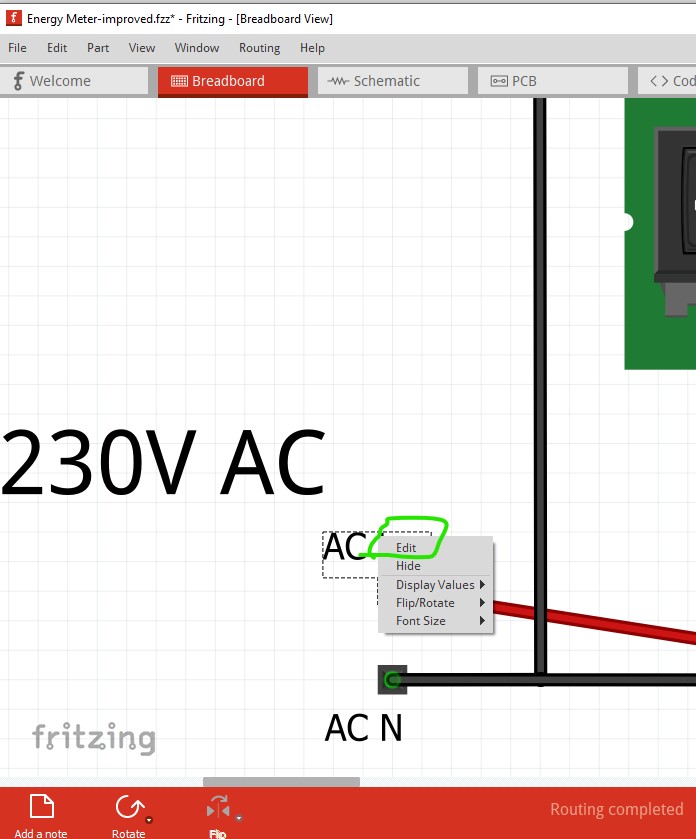
You have a few more problems as well. In this sketch I added single pin headers to all the AC lines. Without them you get no pads in pcb to connect wires.
This is a single pin header which will produce a solder tab with a hole in pcb. I changed the label to tell you what it represents (so you can tell which is which in pcb.) To change that right click on the label and click edit
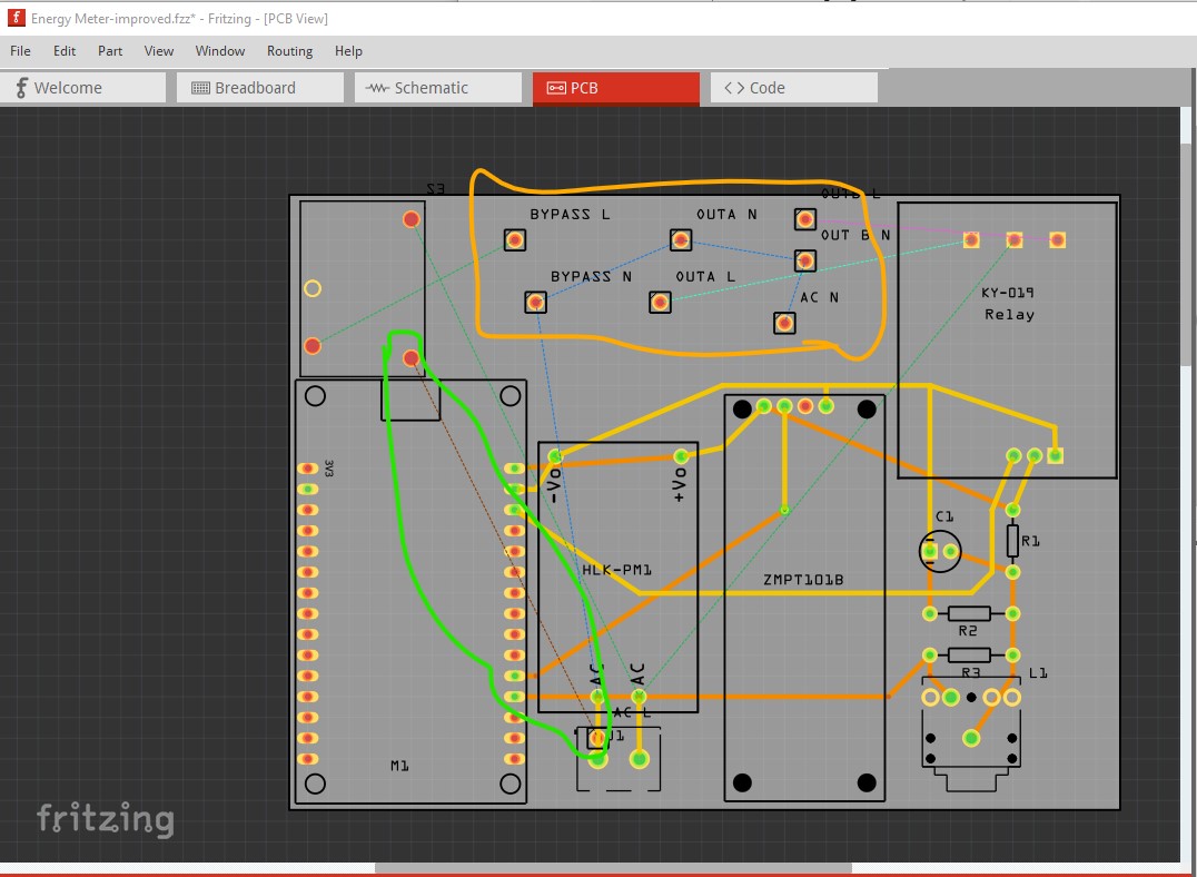
That adds some connectors in schematic and pcb (I also deleted the 240V net labels which are schematic only as they won’t reflect in pcb unlike the headers.) That leaves some pads to place and route in pcb like this:
the rats nest lines (circled in green) indicates where you need to add traces, clicking on it and moving the mouse will create a trace. The headers (circled in orange) need to be placed where you want the wires to connect and then routed according to the rats nest lines. Once that is all done you need to run DRC (which currently breaks) like this:
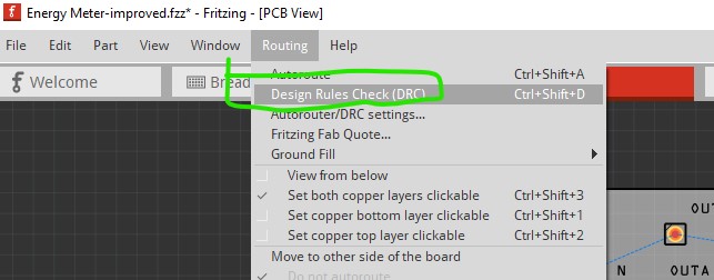
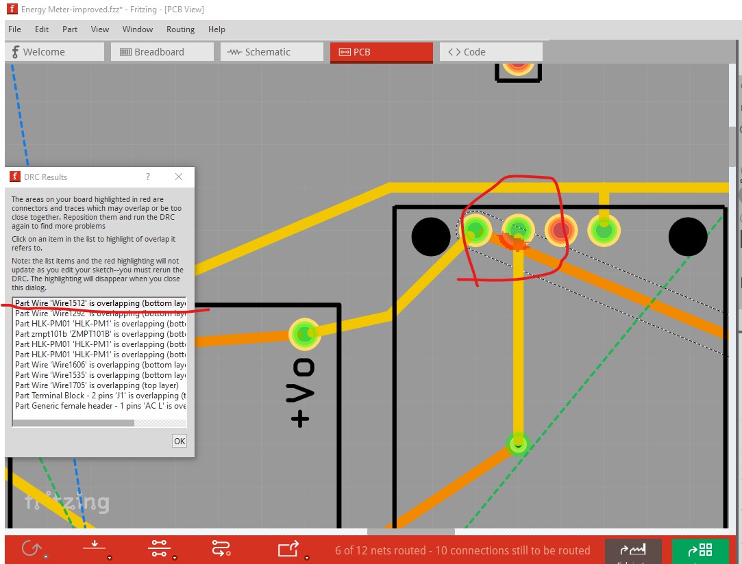
Which will check you pcb layout for errors (which it finds here)
Here it is trying to tell you that the trace marked in red is shorting to the pin on the module which it should not be. The others will be similar. Here is a sketch with these changes made in it.
Energy Meter-improved.fzz (120.8 KB)
Peter
I shouldn’t have left the illustration wires that misled you.
I don’t thnk I need single pin headeron the output of the relay (OUTA N/L, OUTB N/L) since I plan to use the terminal block of it.
I think that should work. The line input would connect to the terminal block on the Hi Link to get the AC on to the board and in to the switch, the ZMT101B appears to have screw terminals too and presumably the wire through the current transformer will connect there as well. You may want to add another 2 pin terminal block to provide a connection point for the bypass output (instead of the single pin headers) Then I think wires from the various screw terminals should be able to complete the circuit.
Peter
Yes, that is how I wired it onto the breadboard.
As for the switch I don’t think I’m gonna put it on the circuit. If I put the circuit into a box, the switch will be on it. So the line input would connect to the switch and to the Hi Link to get the AC on to the board.
The SCT013 on the circuit board view is a female jack right ?
Do you think the widths of the tracks are wide enough ?
What pcb service do you recommend for Europe (France) ? Aisler ?
Thanks again Peter.
Energy Meter.fzz (110.4 KB)
I don’t know. From the footprint it looks like it may be but it is hard to tell. Your best bet would be to buy the connector you intend to use and see if it fits the footprint in pcb (if it doesn’t the board won’t work.)
There doesn’t appear to be anything high current there, so the traces should be fine.
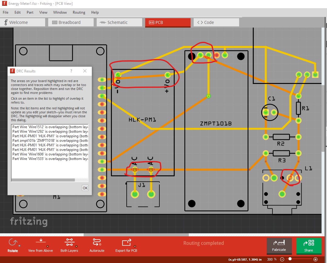
I rarely make boards and use Elcrow in China when I do (which takes a couple of weeks to a month usually.) Folks here have had good experience with Aisler but I haven’t used them. Your board still has a number of DRC errors and as it stands won’t work. There is a short across the AC line and on the Hi Link output and in the current transformer connector.
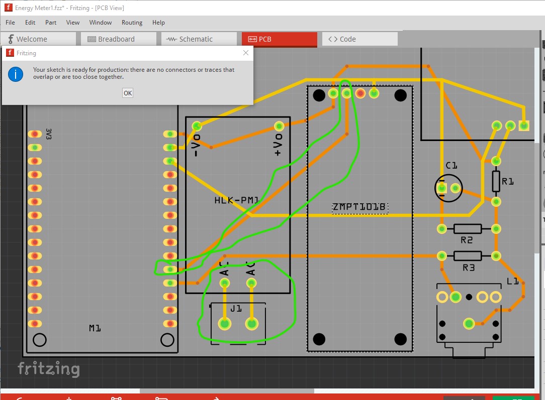
here is a corrected version that passes DRC
Energy Meter1-fixed.fzz (111.8 KB)
and what pcb now looks like.
I rerouted the trace circled in green to eliminate the via and moved the ones that were shorting to have enough clearance.
Peter
I did autoroutage but I forgot to use the drc like you said before, sorry. I understand fritzing better now thanks to you, bless you.
Slimane.