ADS1115 16-Bit ADC - 4 Channel with Programmable Gain Amplifier
I know there is already a ADS1115 however there isn’t one with the above spec and pin configurations - Could someone please help me create this part if possible
ADS1115 16-Bit ADC - 4 Channel with Programmable Gain Amplifier
I know there is already a ADS1115 however there isn’t one with the above spec and pin configurations - Could someone please help me create this part if possible
Hi,
There is an existing part here
@kit2002 please do not download as there are issues with it.
@vanepp can you please help to fix the part and post the corrected one? (the most immediate problem is described here:
I’m not sure if there are any more problems…
I could fix this, but I don’t think it is what he wants. He requested the chip itself not a breakout board. The fix on the adafruit part is easy you just need to add terminalIds in schematic. The part will work fine as is it the connection is straight in rather than at an angle as shown.
Peter
Well, since he posted the datasheet of the ADS1115 16-Bit ADC STEMMA, he might probably want the breakout board I guess. It’ll also be good to fix up Adafruit’s part ![]()
Looking at the part, there are 3 grounds (Pin 1, 5, and 16), 3 VCCs (Pin 2, 6, and pin 15) as well as other overlapping connectors
@kit2002 do you want the chip, or the breakout board?
the breakout board please - the original file you sent looks good. Guess its just whatever issues you think need fixing
Thanks for the help
No prob! Currently redoing the svg…
I’m halfway done (or even less) with the svg (I’m redoing it with randy’s inkscape extension)

Adafruit ADS1115 16-Bit ADC STEMMA-incomplete.fzpz (22.0 KB)
Note that the incomplete part above has yet to implement the SVG
(PS can we just not have the overlapping pin method! That would be a lot easier…)
@vanepp can you help me make the part?
If by ‘overlapping pin method’ you mean things like the multiple ground pins at the same location in schematic, that is needed for the latest version of Fritzing that I have used, to prevent certain types of issues. If other views have wires to different grounds pins the rats nest lines for schematic get messed up. Or they used to at least. To me only one pin should be needed in schematic for a single bus. All of the ‘internally connected’ pins should be treated as a single pin in schematic. But it did not actually work that way in my testing.
That issue is accepted on github as a bug, so may get fixed. I just opened an issue about the same thing (that I am about to close) and got directed to the open ticket.
Peter
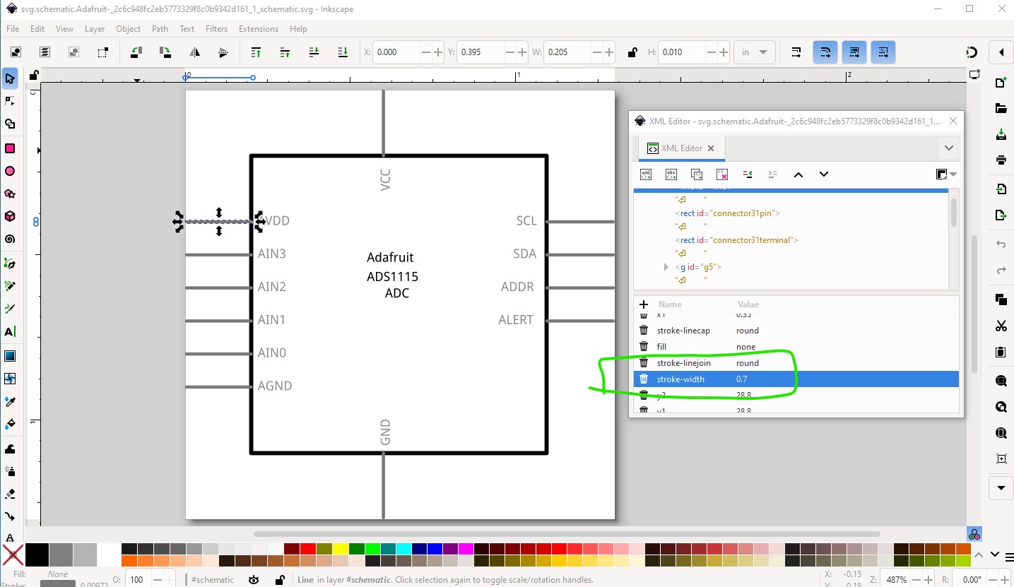
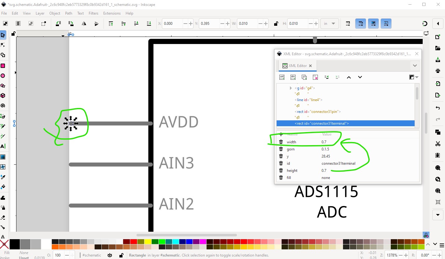
The easy way is modify the current schematic svg like this. The problem is that the terminalId has a 0 width, changing it to match the height will correct the problem
from
to
then do the same for the rest of the terminalIds. You do need to check that the modified terminalIds are correctly positioned on the end of the line as sometimes the x or y coords will be wrong.
Peter
OK, Now I face a bigger problem.
In the PCB view, the connectors are named wrongly

Here is the PCB SVG:

I’m done cleaning up the breadboard view (svg here)

Edit:
I have compiled the svgs into the part (though I have not defined PCB connectors as I need help with that)
Adafruit ADS1115 ADC-almostDone.fzpz (25.3 KB)
I also have been thinking of just leaving the THT connectors and suppressing the QWIIC connectors in PCB view, but keeping them in the breadboard and schematic views. How do I do it? Can you post the completed part once you’re done?
OK here is a fixed up part and what I did to fix it. Starting in breadboard there are a variety of issues. This part was likely made from eagle 2Fritzing and not cleaned up as it has extra connectors and groups (which are not needed)
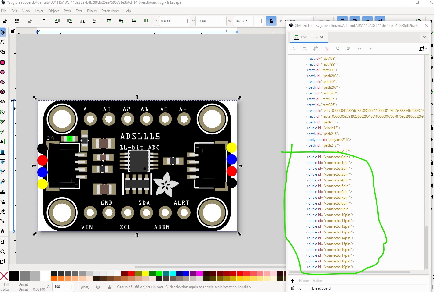
so start by moving the pins to the bottom of the svg (so the tools that renumber svgs work)
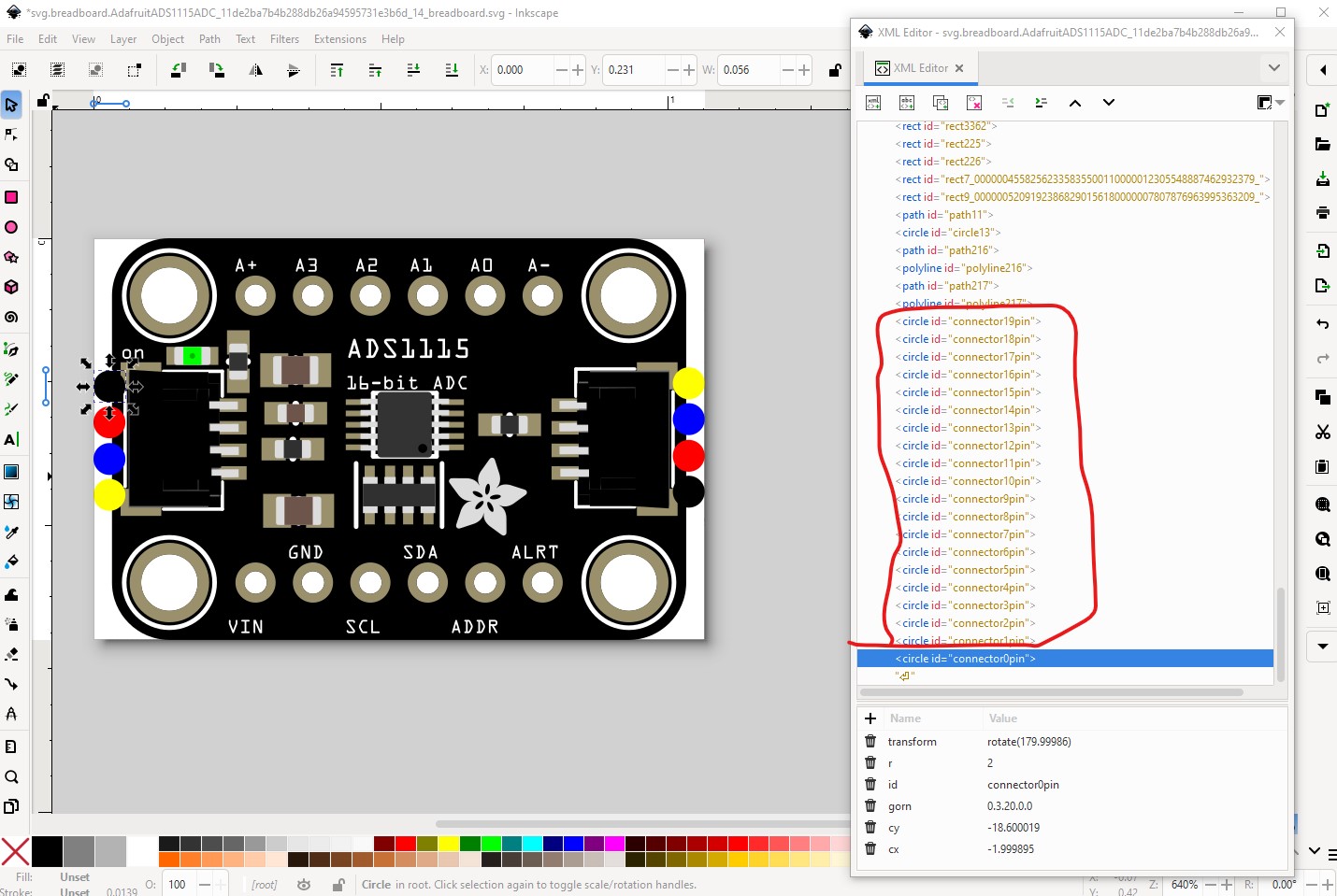
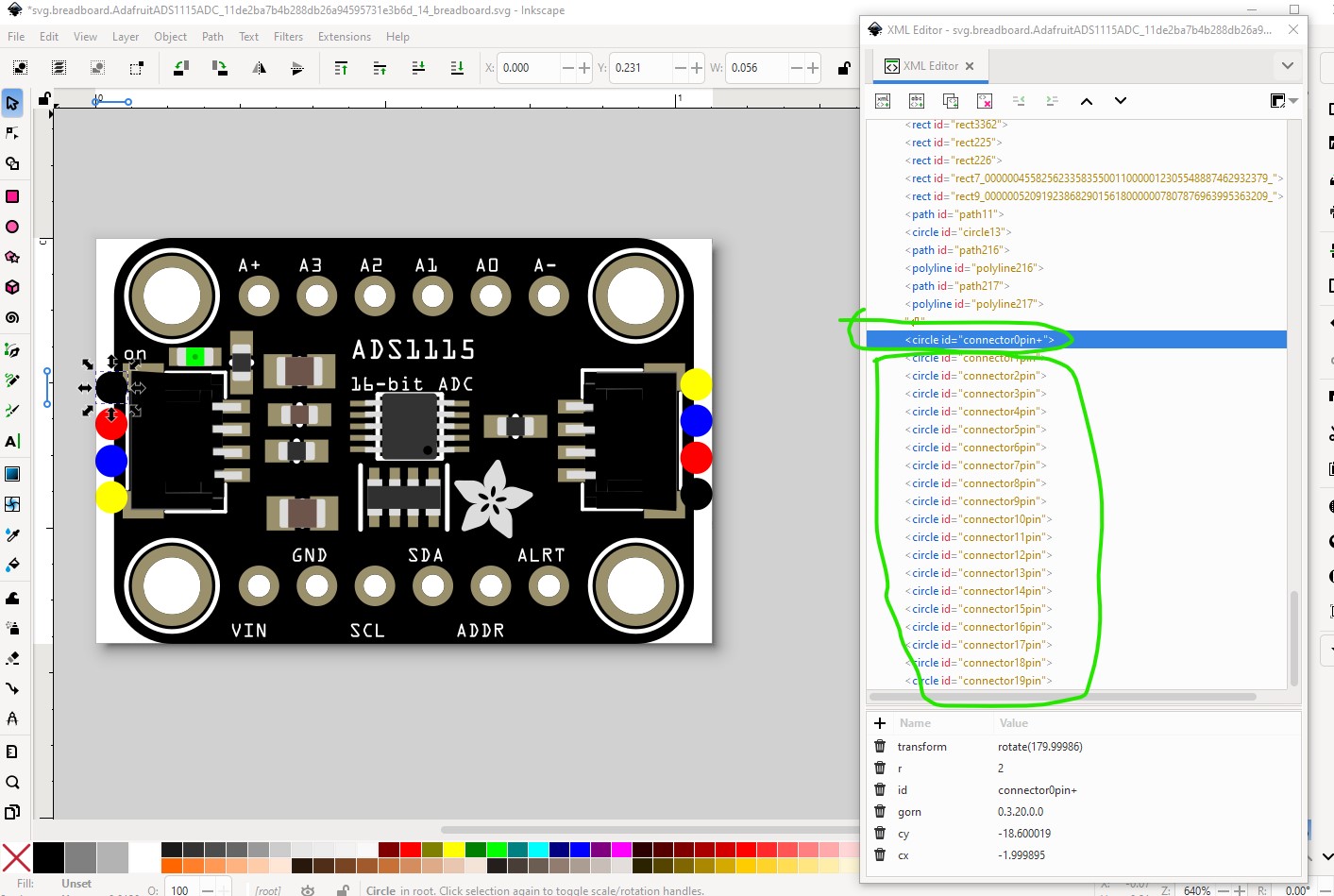
after that relabel connector0pin to connector0pin+ which is needed for E2fRemoveUnusedConnectors.py (which isn’t currently publicly available as it needs work) to unlabel the unused connectors.
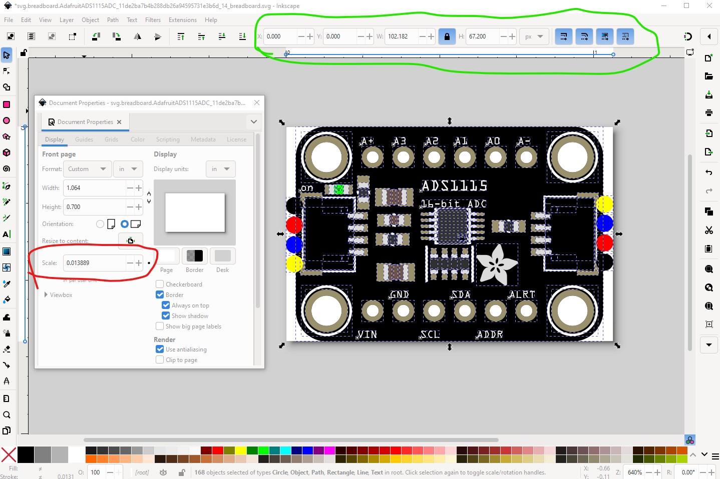
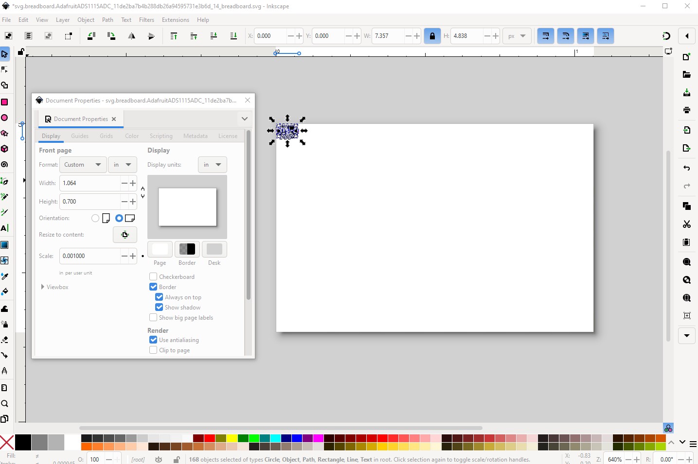
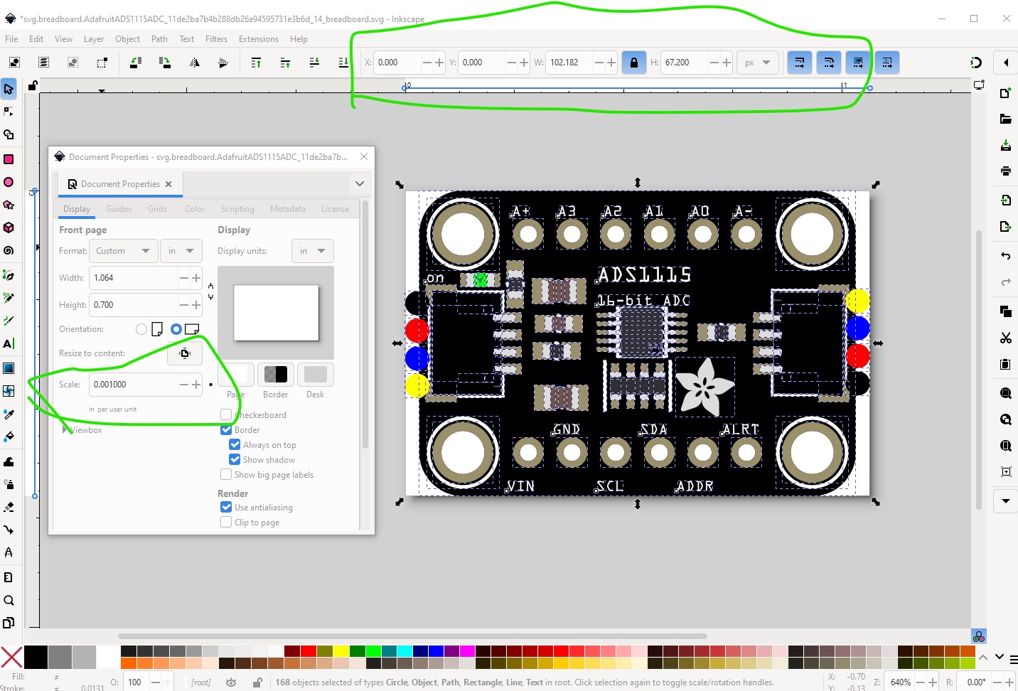
then ungroup the entire svg, reset its view box and rescale the svg to be the correct scale as specified in the graphic standards. The svg will work without this, but it isn’t correct.
so now we are at the correct scale so regroup the svg and set the breadboard layerid then save it.
then run E2fRemoveUnusedConnectors.py to clean up the svg by changing the names of the elements with “connector” to generic element names such as rectangle1 or circle1. Despite the message the connectors are not deleted just renamed.
$ E2fRemoveUnusedConnectors.py svg.breadboard.AdafruitADS1115ADC_11de2ba7b4b288db26a94595731e3b6d_14_breadboard.svg
*** Process svg.breadboard.AdafruitADS1115ADC_11de2ba7b4b288db26a94595731e3b6d_14_breadboard.svg ***
line 1597 connector ‘connector23pin’ deleted as unused.
line 1606 connector ‘connector24pin’ deleted as unused.
line 1631 connector ‘connector27pin’ deleted as unused.
line 1640 connector ‘connector28pin’ deleted as unused.
line 1649 connector ‘connector43pin’ deleted as unused.
line 1658 connector ‘connector44pin’ deleted as unused.
line 1667 connector ‘connector45pin’ deleted as unused.
line 1676 connector ‘connector46pin’ deleted as unused.
line 1685 connector ‘connector47pin’ deleted as unused.
line 1694 connector ‘connector48pin’ deleted as unused.
line 1703 connector ‘connector49pin’ deleted as unused.
line 1712 connector ‘connector50pin’ deleted as unused.
line 1721 connector ‘connector51pin’ deleted as unused.
line 1730 connector ‘connector52pin’ deleted as unused.
line 1771 connector ‘connector57pin’ deleted as unused.
line 1780 connector ‘connector58pin’ deleted as unused.
line 1789 connector ‘connector59pin’ deleted as unused.
line 1798 connector ‘connector60pin’ deleted as unused.
line 1807 connector ‘connector61pin’ deleted as unused.
line 1816 connector ‘connector62pin’ deleted as unused.
line 1825 connector ‘connector63pin’ deleted as unused.
line 1834 connector ‘connector64pin’ deleted as unused.
line 1843 connector ‘connector65pin’ deleted as unused.
line 1852 connector ‘connector66pin’ deleted as unused.
line 2254 connector ‘connector0pin+’ changed to ‘connector0pin’.
line 2262 connector ‘connector1pin’ changed to ‘connector1pin’.
line 2270 connector ‘connector2pin’ changed to ‘connector2pin’.
line 2278 connector ‘connector3pin’ changed to ‘connector3pin’.
line 2286 connector ‘connector4pin’ changed to ‘connector4pin’.
line 2294 connector ‘connector5pin’ changed to ‘connector5pin’.
line 2302 connector ‘connector6pin’ changed to ‘connector6pin’.
line 2310 connector ‘connector7pin’ changed to ‘connector7pin’.
line 2318 connector ‘connector8pin’ changed to ‘connector8pin’.
line 2326 connector ‘connector9pin’ changed to ‘connector9pin’.
line 2333 connector ‘connector10pin’ changed to ‘connector10pin’.
line 2341 connector ‘connector11pin’ changed to ‘connector11pin’.
line 2349 connector ‘connector12pin’ changed to ‘connector12pin’.
line 2357 connector ‘connector13pin’ changed to ‘connector13pin’.
line 2365 connector ‘connector14pin’ changed to ‘connector14pin’.
line 2373 connector ‘connector15pin’ changed to ‘connector15pin’.
line 2381 connector ‘connector16pin’ changed to ‘connector16pin’.
line 2389 connector ‘connector17pin’ changed to ‘connector17pin’.
line 2397 connector ‘connector18pin’ changed to ‘connector18pin’.
line 2405 connector ‘connector19pin’ changed to ‘connector19pin’.
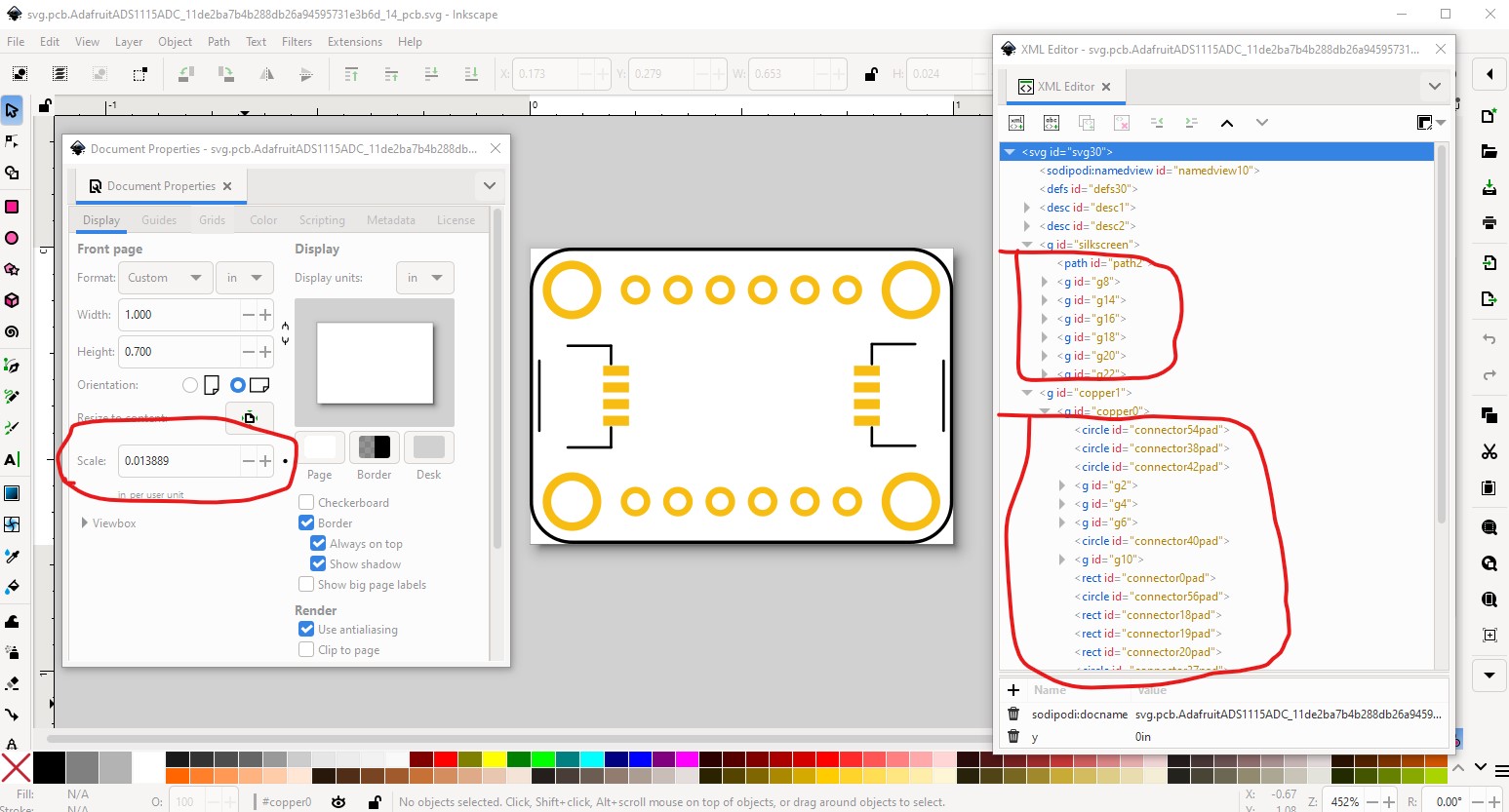
Now breadboard is done. Schematic (as it was created by Randy’s extension) is fine as is. So on to pcb, first the scale is wrong
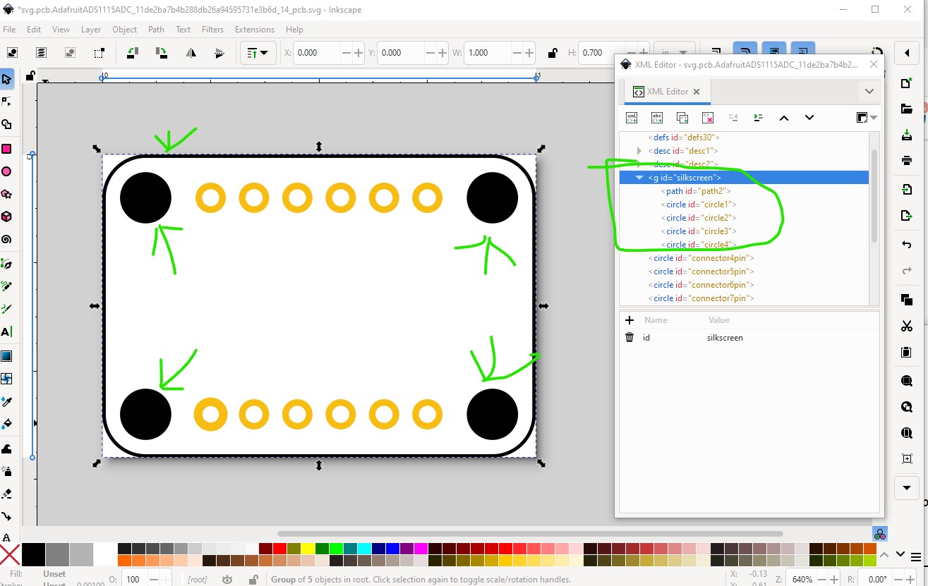
and the mounting holes as set will be drilled (which is undesirable, as to remove them you need to modify the part) so change them to be on silkscreen only (where you can drag a core parts pcb hole over them if you want them drilled or leave them alone on silkscreen if you don’t want then drilled) and change their names from connectorxx to circle1 to circle4.
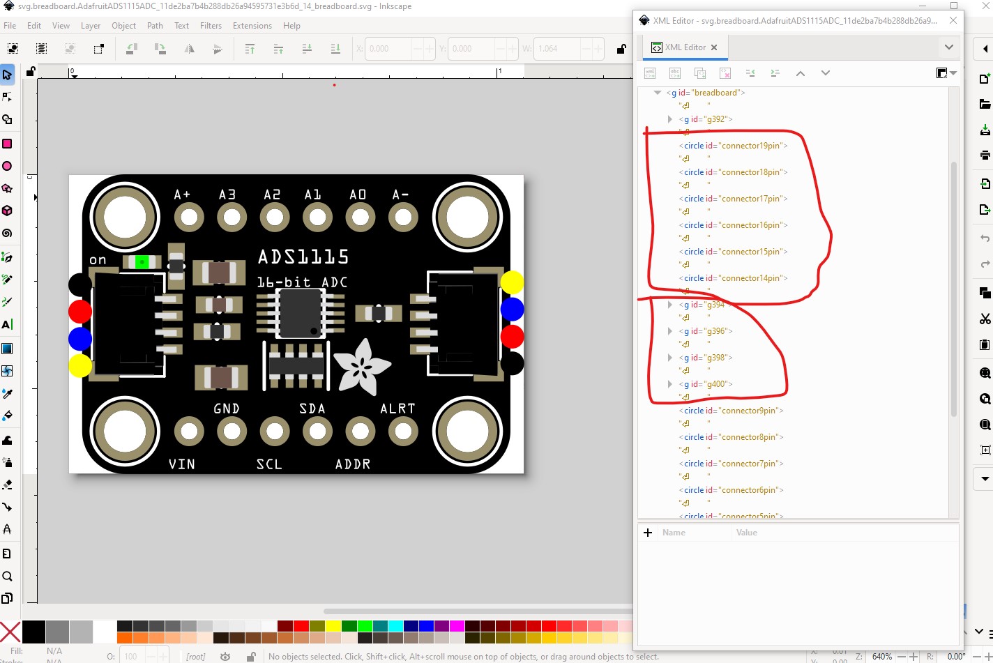
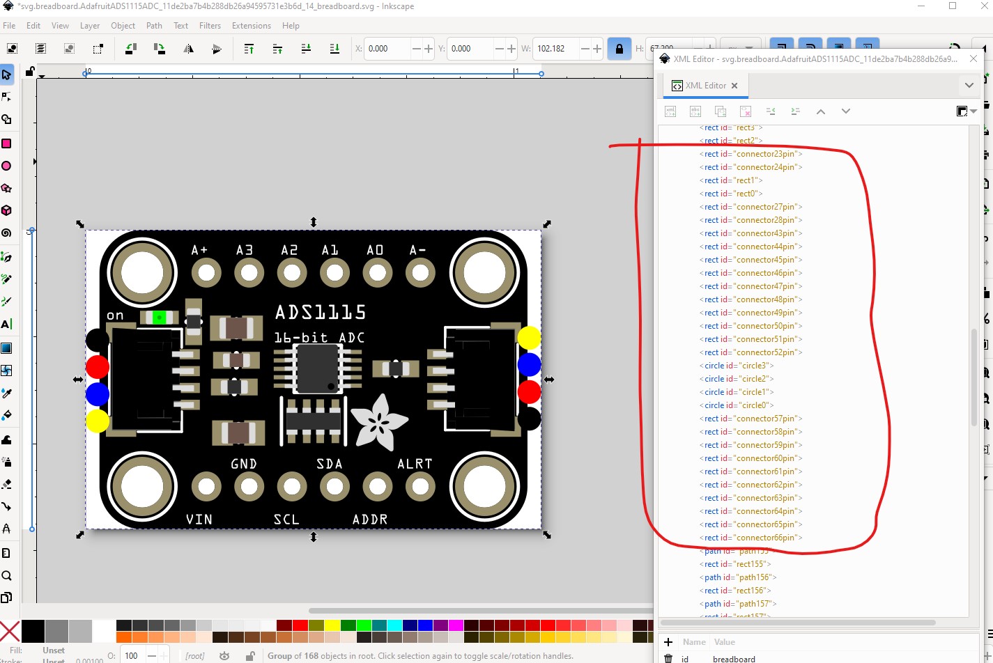
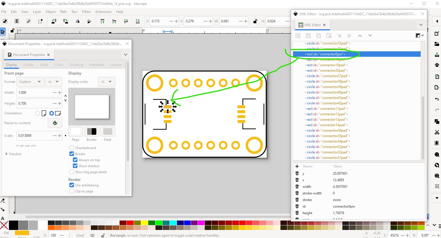
but first we need to set the pins starting with connector0pin to renumber them, note they need to be in the same order as breadboard and schematic as the pin numbers in all three views must match! We will then delete the two grove connectors to remove them in pcb but leave the other pin numbers correct. At the same time set connector0pin to connector0pin to run setbb,py to renumber the pins.
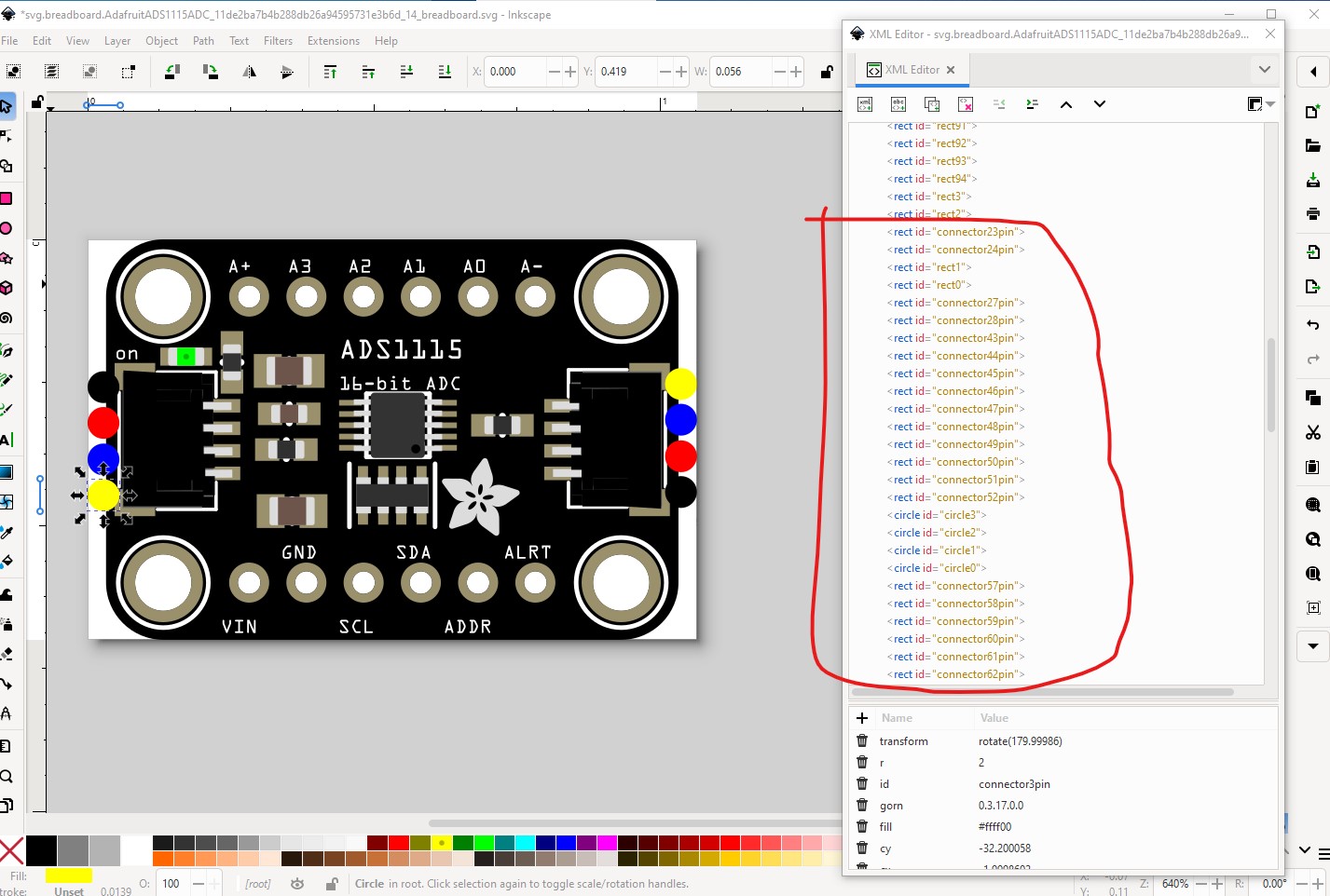
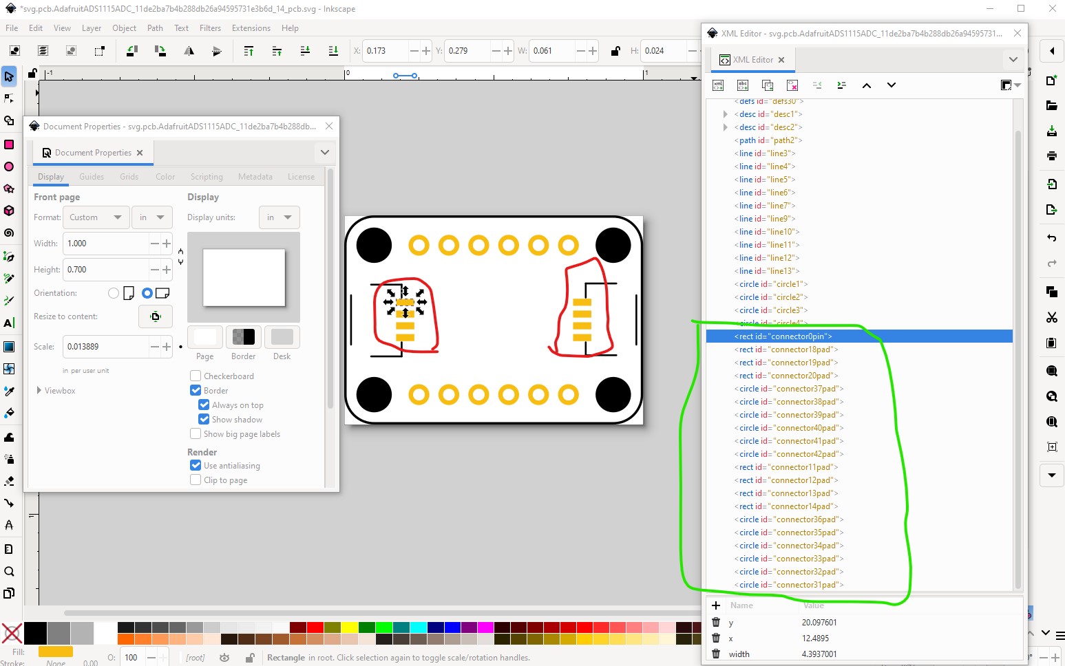
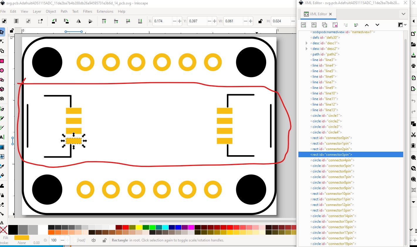
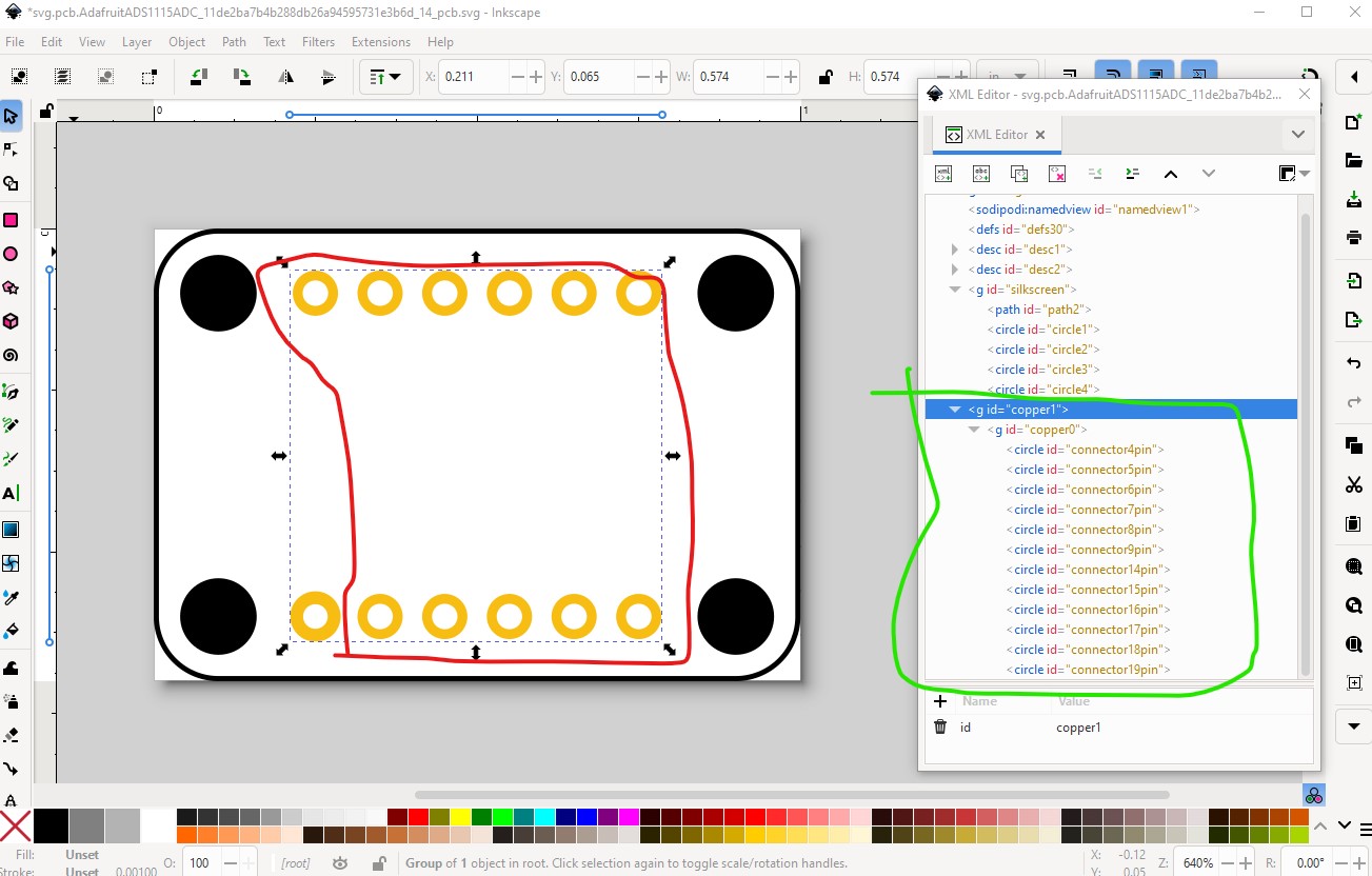
this is the svg (with the grove connectors present) that we are going to run setbb.py against. That will correctly renumber the pins. Then we are going to delete the part circled in red here to remove the grove connectors from pcb.
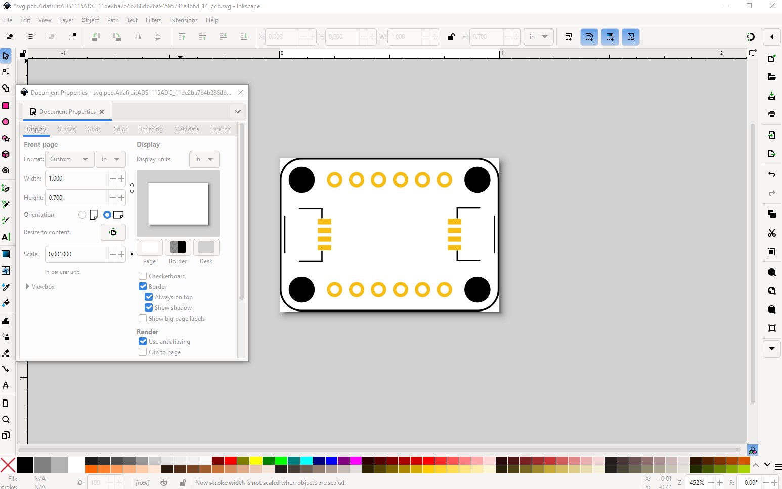
but first rescale the board (which is in the appropriate ungrouped state to do that) to the standard scale.
then save the svg and run setbb.py to renumber the pins.
$ setbb.py svg.pcb.AdafruitADS1115ADC_11de2ba7b4b288db26a94595731e3b6d_14_pcb.svg
*** Process svg.pcb.AdafruitADS1115ADC_11de2ba7b4b288db26a94595731e3b6d_14_pcb.svg ***
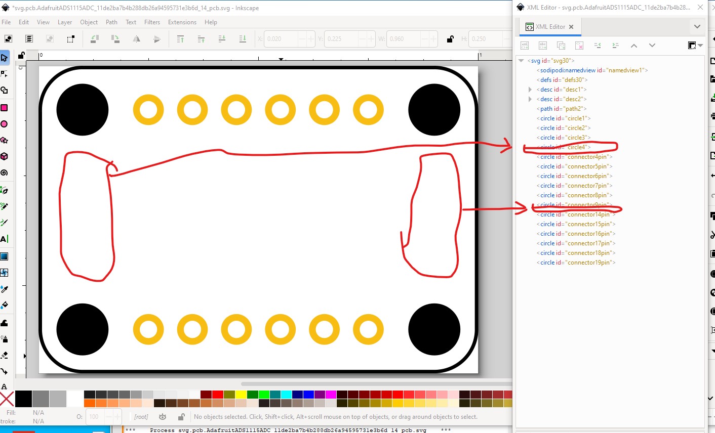
then delete the unwanted connectors (the two grove connectors)
leaving the others with their correct pin numbers.
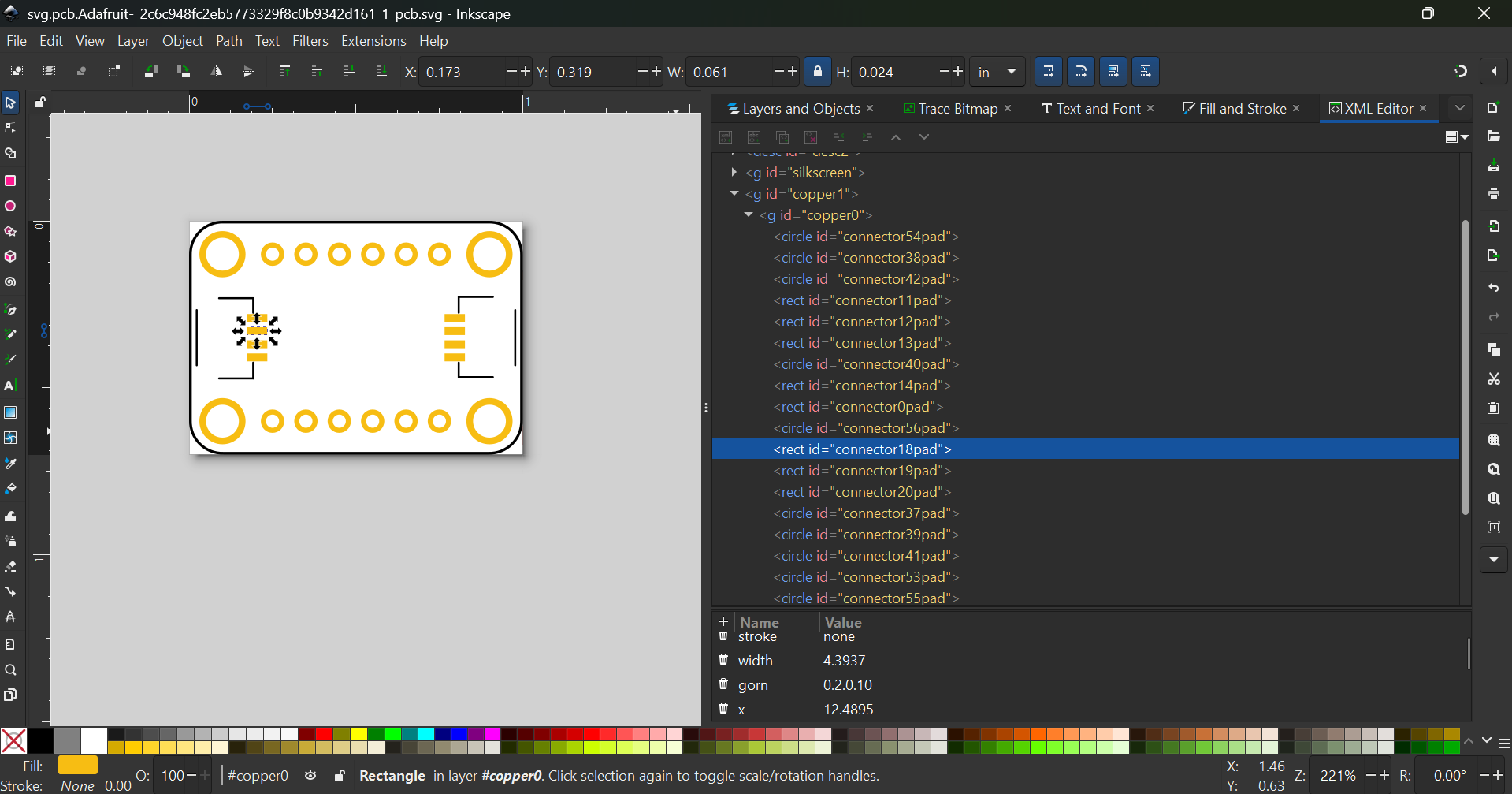
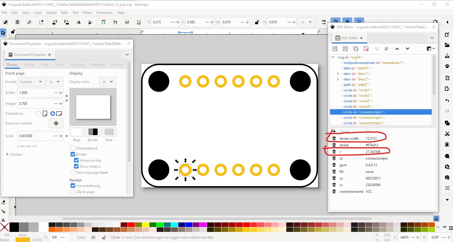
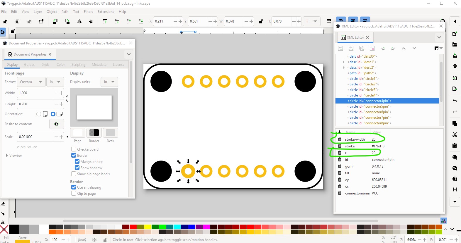
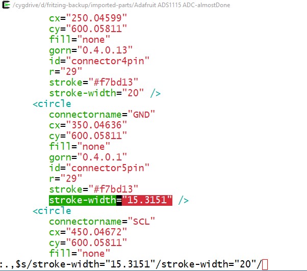
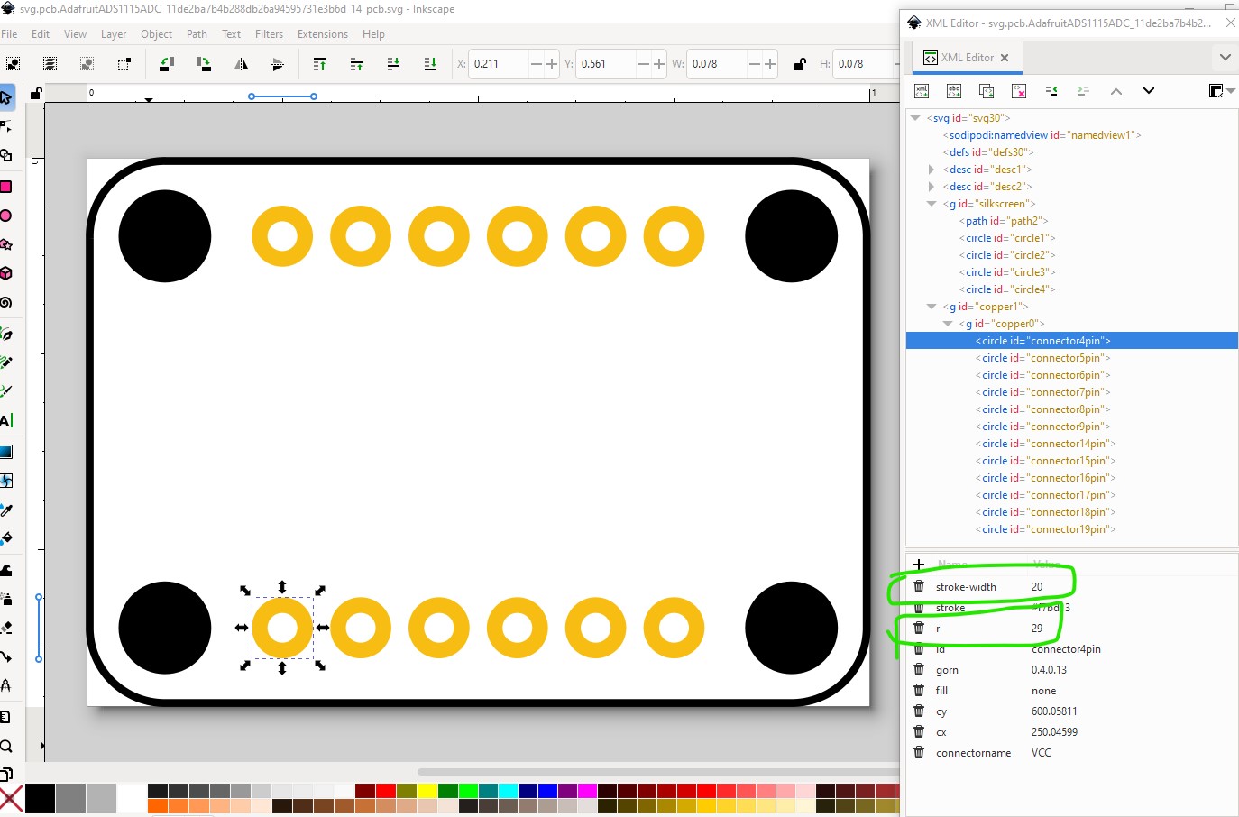
now we are at the correct scale, check the size of the pads (which are incorrect.) To match a standard 0.1in header (which is what we want) the radius of the circle needs to be 29 and the stroke-width 20 (which they currently are not.) So here I changed one instance as an example
to this
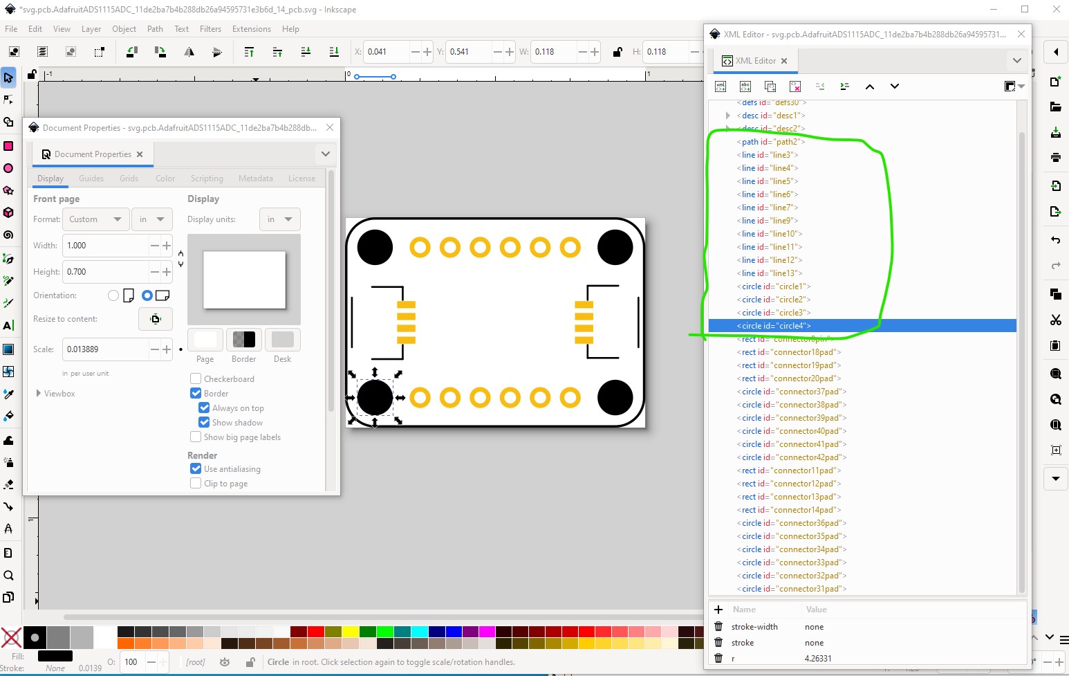
then group the path and 4 circles in to the silkscreen group
and then the two copper groups (note the pads circled in red are the wrong size still!)
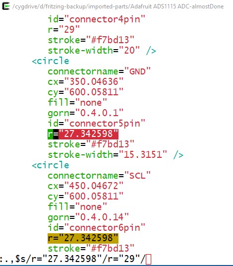
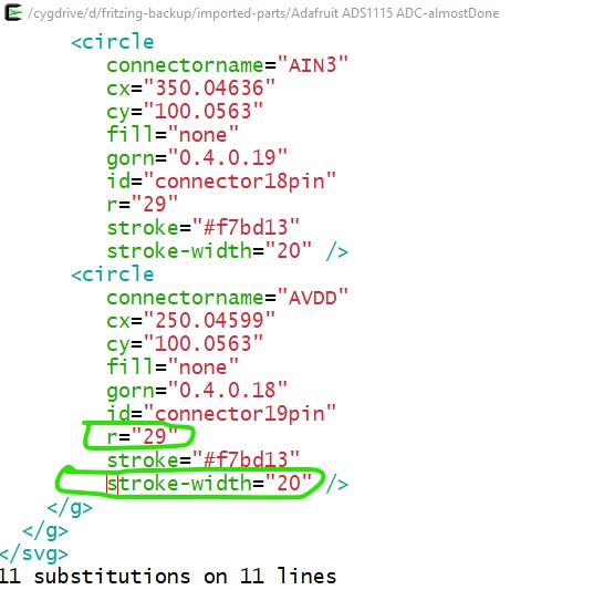
to correct the other pads I save the svg and then edit with a text editor (vi in this case) and do a global replace of the stroke-width and radius of the pads still incorrect like this: radius from 27.342598 to 29
and stroke-width from 15.3151 to 20
which corrects all the pads. So save the svg then load it in to Inkscape to make sure all went well.
Now I need to modify the .fzp file to reflect the removal of the grove connectors (which can’t be done in parts editor AFAIK) like this. Edit the fzp file with a text editor (here vi)
vi part.AdafruitADS1115ADC_11de2ba7b4b288db26a94595731e3b6d_14.fzp
and change the connector definitions like this
from
 <connectors>
  <connector id="connector0" name="GND" type="pad">
   <description>pin 1</description>
   <views>
    <breadboardView>
     <p layer="breadboard" svgId="connector0pin" terminalId="connector0terminal"/>
    </breadboardView>
    <schematicView>
     <p layer="schematic" svgId="connector0pin" terminalId="connector0terminal"/>
    </schematicView>
    <pcbView>
     <p layer="copper0" svgId="connector0pin"/>
     <p layer="copper1" svgId="connector0pin"/>
    </pcbView>
   </views>
  </connector>
to
 <connectors>
  <connector id="connector0" name="GND" type="female">
   <description>pin 1</description>
   <views>
    <breadboardView>
     <p layer="breadboard" svgId="connector0pin" />
    </breadboardView>
    <schematicView>
     <p layer="schematic" svgId="connector0pin" terminalId="connector0terminal"/>
    </schematicView>
    <pcbView>
    </pcbView>
   </views>
  </connector>
where the pin type changed from pad to female for the grove connectors (so if you place the part on a breadboard the grove connector terminals will not connect to the breadboard because they are female as is the breadboard and thus not short!) , the terminalId in the breadboard definition on all connectors got removed (because it isn’t in the svg and thus isn’t used but FritizngCheckPart.py will complain about it!), and only in the case of the grove connectors, the pcb pin definitions got deleted to make them not appear in pcb. You can remove the pcbView definition completely, but this makes it easier to add the pads back in if you need to for some reason.
I changed the bus definition from internal1 to internal4 to
   <buses>
  <bus id="GND">
   <nodeMember connectorId="connector0"/>
   <nodeMember connectorId="connector5"/>
   <nodeMember connectorId="connector10"/>
  </bus>
  <bus id="VIN">
   <nodeMember connectorId="connector1"/>
   <nodeMember connectorId="connector4"/>
   <nodeMember connectorId="connector11"/>
  </bus>
  <bus id="SDA">
   <nodeMember connectorId="connector2"/>
   <nodeMember connectorId="connector7"/>
   <nodeMember connectorId="connector12"/>
  </bus>
  <bus id="SCL">
   <nodeMember connectorId="connector3"/>
   <nodeMember connectorId="connector6"/>
   <nodeMember connectorId="connector13"/>
  </bus>
  </bus>
 </buses>
which labels the group with the connector description and puts the groups in order. Neither of those matter particularly it is just cleaner and easier to modify later if needed. As well I added a url for where you can get the board
<url>https://www.adafruit.com/product/1085</url>
which is a good practice for all parts. That completes the fzp file modifications and now run the new part through FritzingCheckPartw.py to check it:
$ FritzingCheckPartw.py part.AdafruitADS1115ADC_11de2ba7b4b288db26a94595731e3b6d_14.fzp
**** Starting to process file Startup, no file yet
**** Starting to process file part.AdafruitADS1115ADC_11de2ba7b4b288db26a94595731e3b6d_14.fzp
**** Starting to process file svg.breadboard.AdafruitADS1115ADC_11de2ba7b4b288db26a94595731e3b6d_14_breadboard.svg.bak
**** Starting to process file svg.schematic.AdafruitADS1115ADC_11de2ba7b4b288db26a94595731e3b6d_14_schematic.svg.bak
**** Starting to process file svg.pcb.AdafruitADS1115ADC_11de2ba7b4b288db26a94595731e3b6d_14_pcb.svg.bak
File
‘part.AdafruitADS1115ADC_11de2ba7b4b288db26a94595731e3b6d_14.fzp.bak’
This is a through hole part as both copper0 and copper1 views are present.
If you wanted a smd part remove the copper0 definition from line 52
Warning 11: File
‘part.AdafruitADS1115ADC_11de2ba7b4b288db26a94595731e3b6d_14.fzp.bak’
At line 58
Type female is not male (it usually should be)
which runs clean with only a warning on the female pin definitions, That results in this corrected part (the moduleId is the same so you will need to delete the current part to load the new one!)
Adafruit ADS1115 ADC-fixed.fzpz (13.1 KB)
You just need to learn what kinds of things (such as 0 width terminalIds) will cause Fritzing problems which should come with experience. You are doing fine in part creation by and large.
Peter
Thank you so much for your detailed explanation! Learnt something new today!