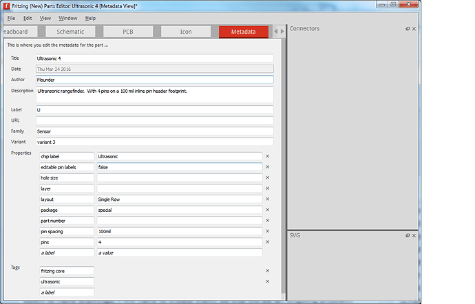
I have a 4-pin device. I would have been happy with a 4-pin mystery device, but there isn’t one. So I started with that one, and have tried to create a 4-pin device. I went into CorelDraw and widened the body, changed the appearance, and did a “copy” of one of the pins followed by a “paste” and “move”. It complained that I had two IDs the same. A bit of poking around revealed how to change the ID of my new connection from a duplicate “connection2” to “connection3”. But when I try to use the part, the fourth pin is not recognized as a connection. I have looked at the XML description, and the descriptions of the pins look the same. I went to the metadata tab
in the parts editor and increased the number of connection pins from 3 to 4, but it still does not recognize the new connection pin; it still only gives me the option of editing only three pins. Since none of the components I want to use seem to have drawings, I will have to create them, so this will be an ongoing problem. For right now, I am working only with the breadboard view; I have not generated the PCB geometry, Schematic symbol, etc., although I will need those in the days to come. The XML file shows no difference between the representations of connection0, connection1, connection2, and connection3. The description is short enough that I’m including it here. I have uploaded a screenshot of the updated part, showing the fact that I have set the number of pins to 4. Unfortunately, your system has decided that as a new user I am entitled to only one image per post, but in the breadboard view I still see only three editable pins. You will have to use your imagination here.<?xml version="1.0" encoding="UTF-8"?>
<!DOCTYPE svg PUBLIC "-//W3C//DTD SVG 1.1//EN" "http://www.w3.org/Graphics/SVG/1.1/DTD/svg11.dtd">
<!-- Creator: CorelDRAW X6 -->
<svg xmlns="http://www.w3.org/2000/svg" xml:space="preserve" width="1.77in"
height="1.02in" version="1.1" shape-rendering="geometricPrecision"
text-rendering="geometricPrecision" image-rendering="optimizeQuality"
fill-rule="evenodd" clip-rule="evenodd"
viewBox="0 0 1770 1020"
xmlns:xlink="http://www.w3.org/1999/xlink"
xmlns:svg="http://www.w3.org/2000/svg"
baseProfile="tiny">
<g id="Layer_x0020_1">
<metadata id="CorelCorpID_0Corel-Layer">
<g id="_777818064">
<rect id="lower" fill="#404040" x="674" y="801" width="377.602" height="30.9606"/>
<rect id="connector0pin" fill="#8C8C8C" x="691" y="801" width="23" height="219"/>
<rect id="connector1pin" fill="#8C8C8C" x="789" y="801" width="23" height="219"/>
<rect id="connector2pin" fill="#8C8C8C" x="891" y="801" width="23" height="219"/>
<rect id="connector3pin" fill="#8C8C8C" x="989" y="801" width="23" height="219"/>
<rect id="upper" fill="navy" y="2" width="1770" height="800"/>
<circle fill="black" stroke="#FEFEFE" stroke-width="41.6654" cx="388" cy="402" r="312"/>
<circle fill="black" stroke="#FEFEFE" stroke-width="41.6654" cx="1388" cy="402" r="312"/>
</g>
</g>
</svg>