I firstly used a perf board in breadboard view to build a little prototype. But I cannot connect solder points from a point which are still connected. In some discussion here there was a tipp to zoom in and try it then but I cannot find any way to connect it.
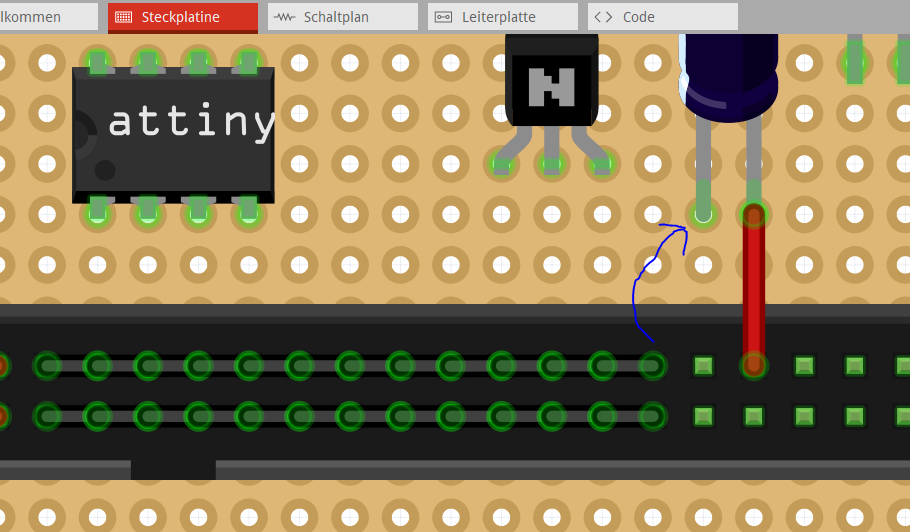
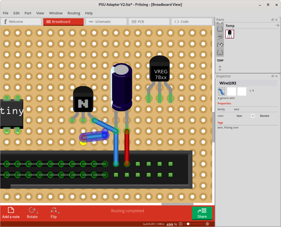
For example I like to create this connection to the IC but I cannot do it that way. Is there a Short-Key?
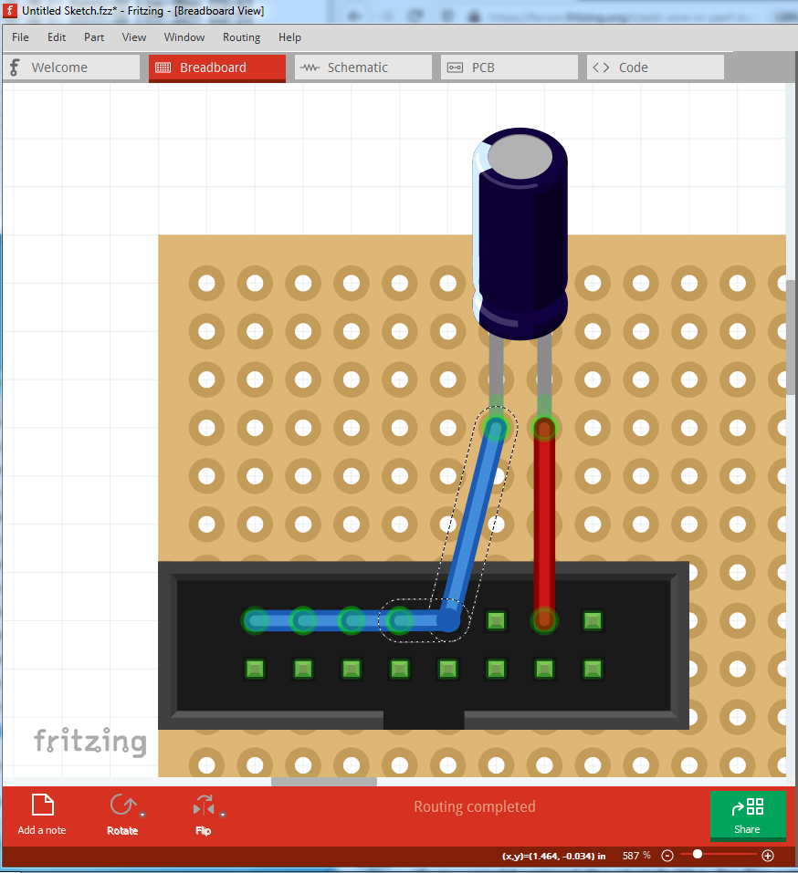
At the end of it all clicking on one of the connections will light everything connected to it up in yellow indicating all the expected connections are there.
The one pin in your example is not connected at the end of the sequence. Attached my example. A pin which is still connected cannot the the start of a new connection it seems for me.
It is true that Fritzing does not like to “start” a wire connection from a connector that already has a wire at it. It wants to pick up the end of the wire, to allow you to move it somewhere else. Here are some tricks / techniques to get the result you want.
Simplest case. Start the wire from the other end. As long as that currently does not have a wire at it.
Start the wire from any existing unused pin or connection pad, and end at the pin you were trying to start from. Then move the start of the wire to where you were intending to end it. Or start from that empty pad and drag to where you want the wire to end, then move the start of the wire from the temporary pad to where you really wanted to start it from.
In the View menu, turn off the “Wires Layer”. With the wires not displayed, they can not be selected, so you actually CAN start wire at a pin that has a (now invisible) wire connected to it. Starting dragging of a wire out from the connection automatically turns the wire layer back on, but by then the wire is already started, to everything works.
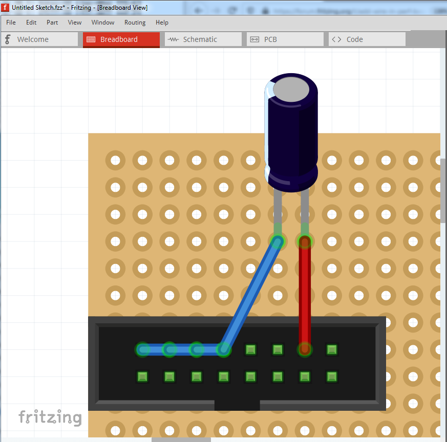
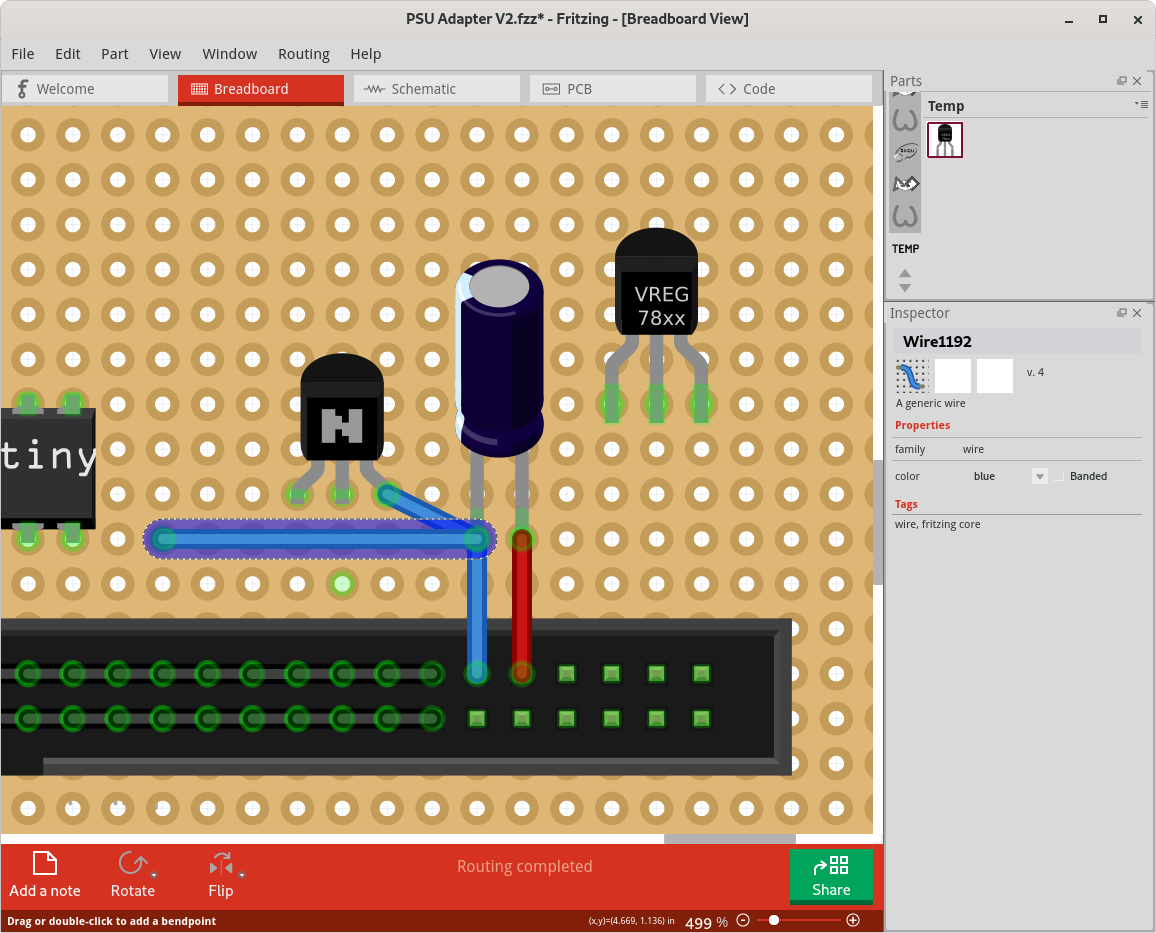
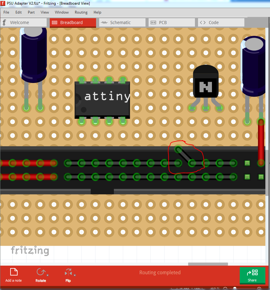
Further to Phil’s comments: your original sketch has a disconnect at this point in the ground wires (click on the left most top ground pin and you will see the yellow stops at the indicated break point):
Here I dragged the existing wire off to a non used pin, then dragged it back to where it belongs to make the connection. After that the entire strip lights up yellow as intended.
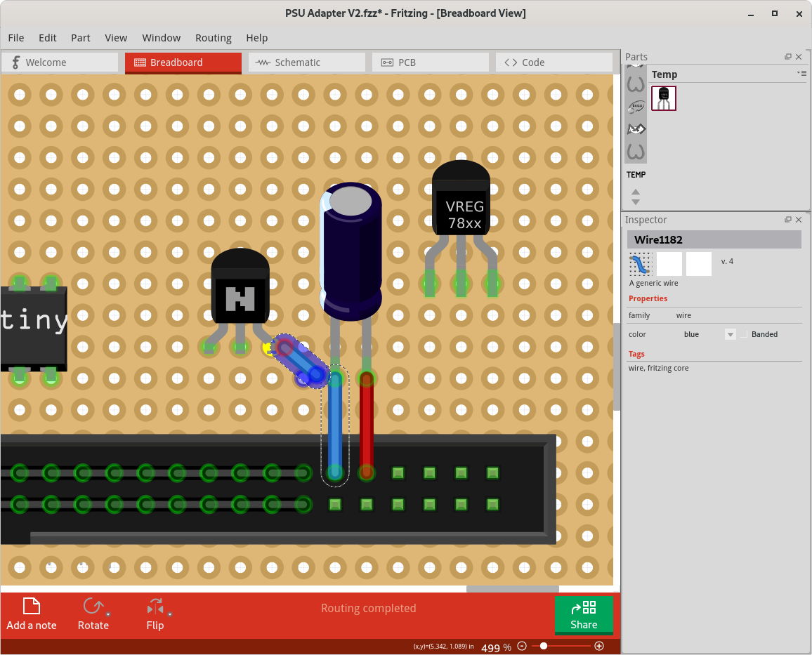
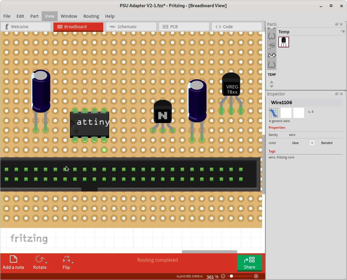
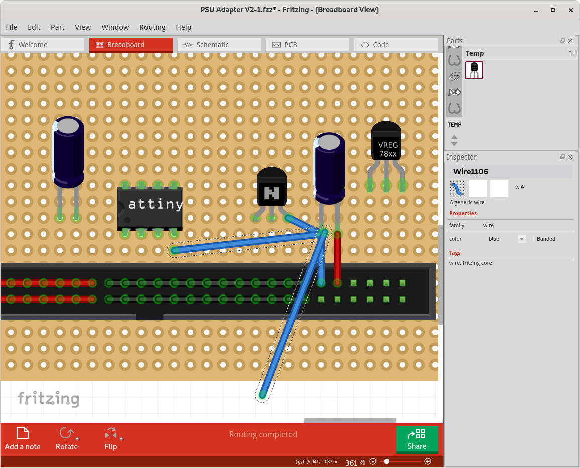
Now do as Phil suggested with the capacitor negative pin (complicated because the capacitor is bendable leg and thus will stretch it’s wire if moved so start from an unused pin and pull in the direction of the arrow):
Thanks a lot for the tipps. I created a small enhancement request to have a shortcut that will create a wire from every connector even has a connection. Would be much better for Prototyping Boards.
Anyhow, there is no option to draw connection on the boards like real ones instead of wires? Did not find anything about it but saw a video on youtube somebody editing the layout of the board. Video Link
One further tip I forgot to mention, you may want to search the forums for parts marked “top view” as there are a bunch of parts that have been modified to suit perfboard better than the conventional ones. Typically LEDs, diodes transistors that exist within the space they take in breadboard rather than the conventional parts which take much more space. As well some folks have used pcb view instead of breadboard as being more suitable to describe perfboard.