I want to know if any one has adafruit v1 motor shield pcb view image since i am making it .If you have, please reply along with the file.
Hindol.
I want to know if any one has adafruit v1 motor shield pcb view image since i am making it .If you have, please reply along with the file.
Hindol.
Have a look at this previous forum post (a google search for “fritzing part adafruit v1 motor shield” turned it up):
Peter
No I want the pcb view image of it.
Hindol
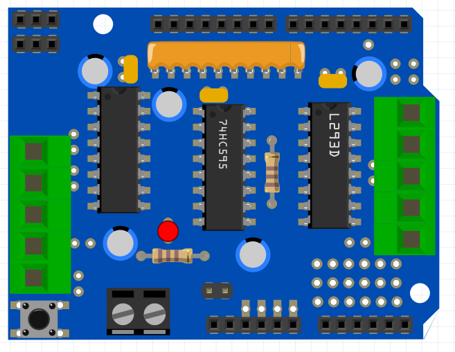
I doubt there is one. The v1 board is obsolete and Adafruit apparently did not make a Fritzing part for it. From this image you should be able to make a pcb image:
https://learn.adafruit.com/assets/1664
although I’m not sure I see a purpose to it. The shield is intended to fit an Arduino UNO, you are not likely to use a pcb with it in Fritzing. With the above image (or better yet a real board) you should be able to place the appropriate pads (copy in a UNO PCB to get the UNO pad layout then add the other pads.)
Peter
Could you make it for me I cannot make pcb images.
Hindol
Could you correct this for me. Some of the pins are not working.Here is the file.
motor shiel.fzz (19.6 KB)
Hindol
I’m not sure what you would want on the pcb image. I’d suggest just suppressing pcb view as being not useful in Fritzing. The connections to the board are via wires to the terminal blocks and servo headers and neither of those are easy to represent in pcb view, showing where they connect in breadboard view seems a lot better alternative to me.
Peter
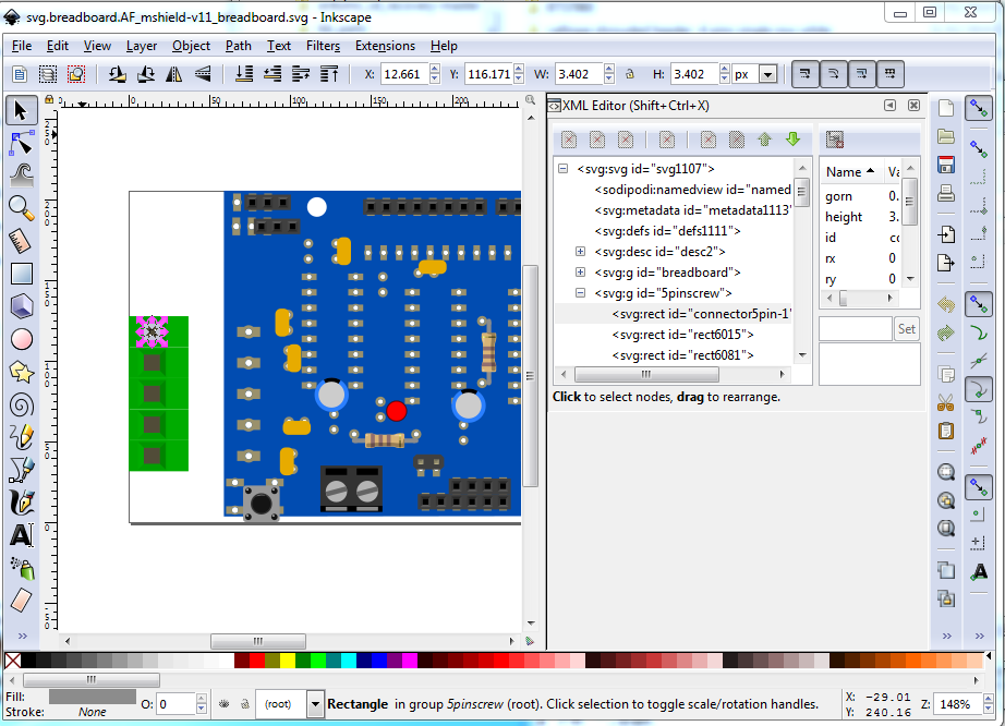
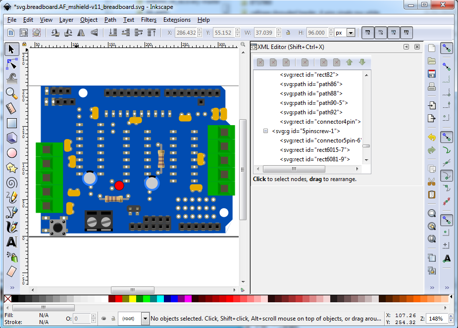
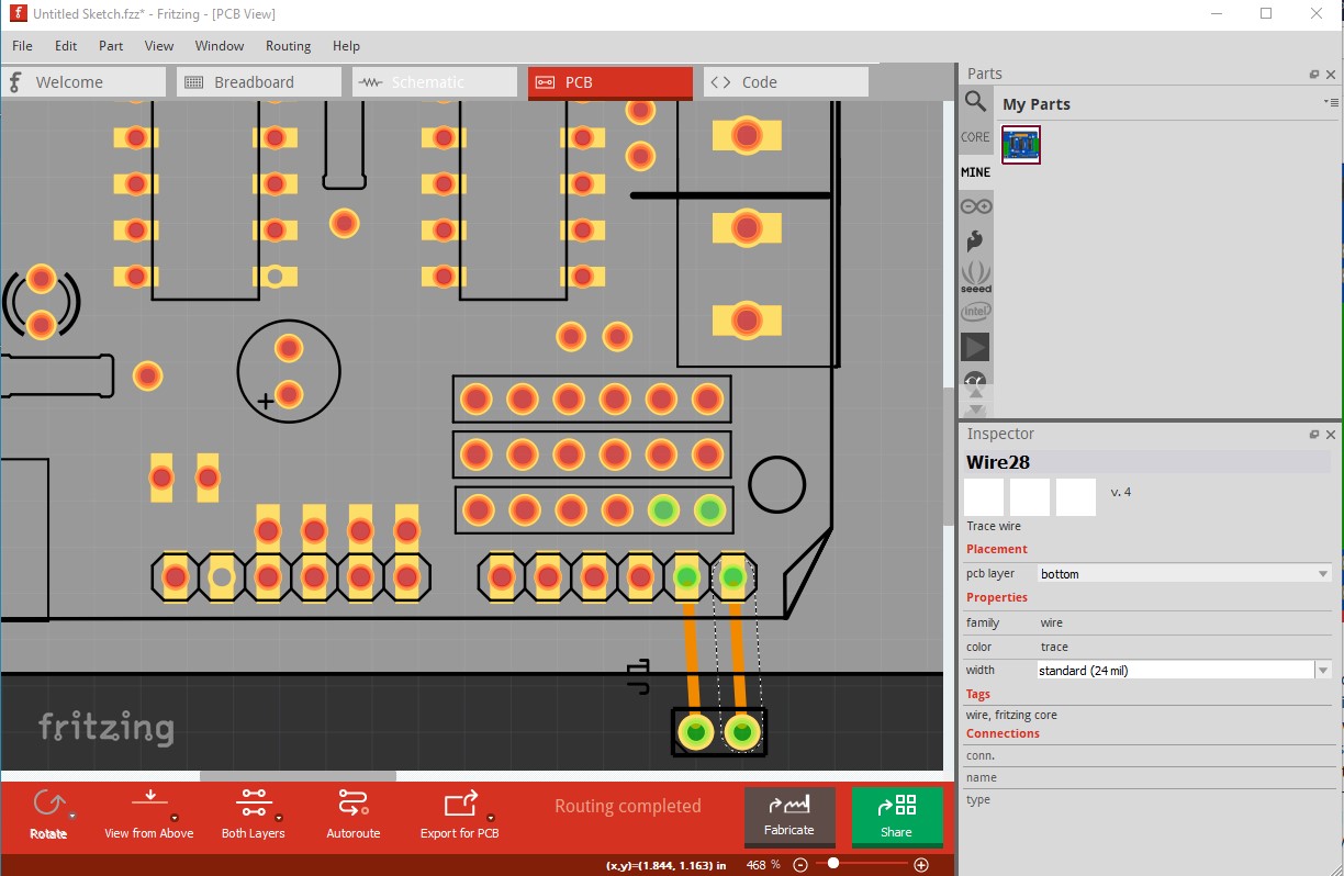
It is your lucky day. Poking around I came across the Eagle board files for the v1 motor driver on github. So I ran the .brd file through Eagle2Fritzing to create a part. It didn’t manage to translate the 5 pin screw terminals, so I copied in 2 Camdenboss CTB0158-5 connectors in to breadboard. Now you need to adjust the connectors (or at least change the connector5pin-1 to connector166pin to match the connection on the board, then do the same for the other 4 connectors on each connector) and move the connector in to position over the solder holes. You also need to move the push button switch as it is slightly misaligned. You could copy in chips to fill the sockets for the ICs if you like. That should give you a part for the shield complete with pcb (although I still think pcb is not useful.)
connectors moved to final position:
adafruit-v1-motor-shield.fzpz (35.7 KB)
Peter
Thanks for your help Peter.
Hindol
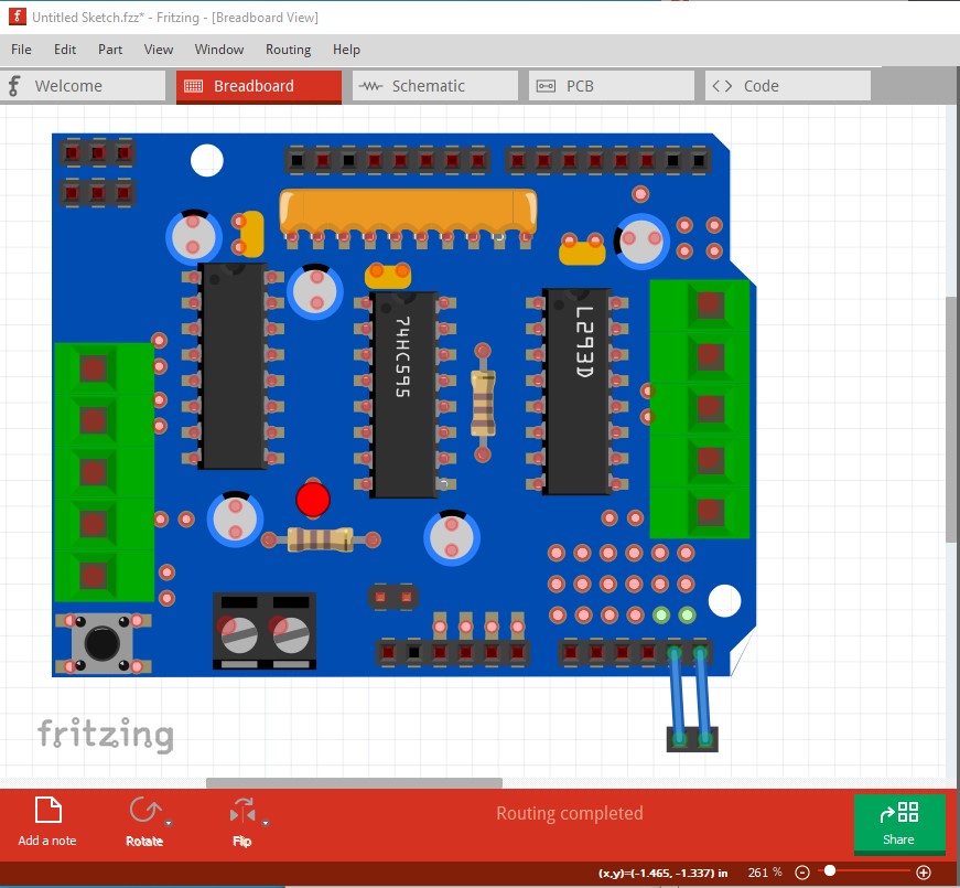
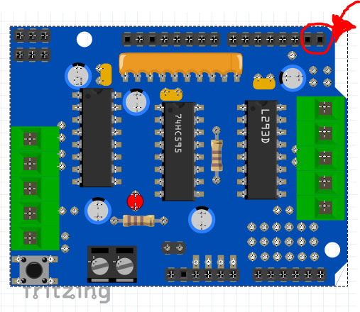
I moved the elements to match the pins, and make it match the model I found.
I did not modify the schematic.
It still needs a lot of work (as usual with Eagle2Fritzing parts.) All the connections in the eagle file are active and to get a proper part you would need to edit them out (although if this works for you, which it may well, then use it as is!) Here I changed the female pins in the fzp file to male so they will show up in red on breadboard. Note that all the internal ICs have Fritzing connections which they should not (you need to manually edit them out which is why I didn’t do that when I posted the original.)
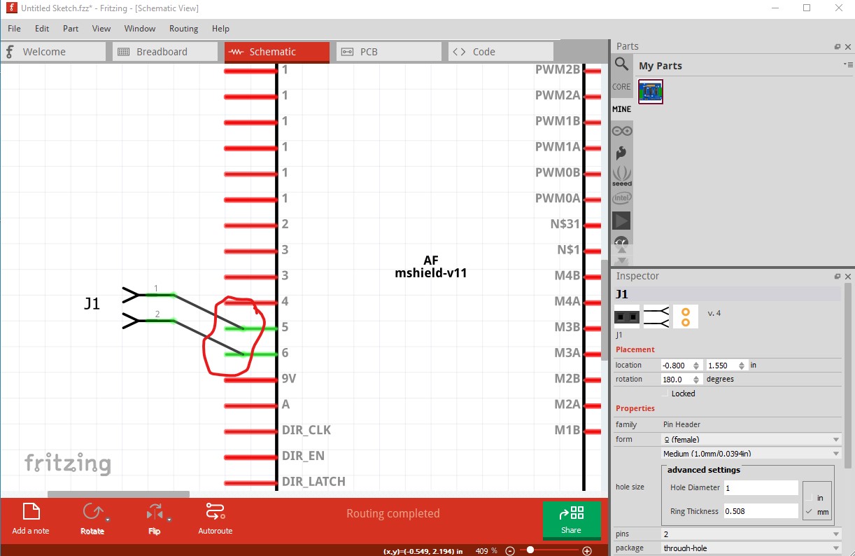
in schematic the terminalIds are either missing or misplaced as the wires are connecting near the middle of the pin (circled in red here)
but the connections appear correct in all views so it may work as is for what you want.
Peter
@vanepp why is there no connections / terminals on these pins? can you add or make it available? thank you!!! needed asap
@vanepp can you help us with the above inquiry? thank uuuu
Yes, although it may take some time as the part needs a fair amount of work to correct.
Peter
@vanepp sorry for my late response but big thank you for this!