Hi, Anyone know if it is possible to “cut” the tracks of the PermaProto board in Fritzing just as it would be if building a project in the real world?
1 Like
On a “stripboard”, clicking on a trace between holes cuts the trace. Clicking again puts it back.
What Fritzing part are you using for a “permaproto” board? The search tool does not find anything to match. If you are using a part from somewhere else, we need access to that to be able to make suggestions.
Hello microMerlin, Thank you for your prompt response to my question.
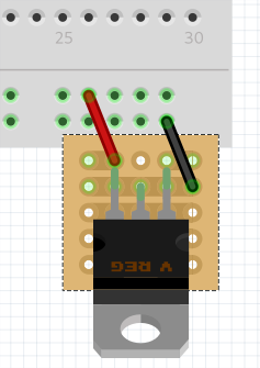
I did in fact find the permaproto board in the Adafruit section of the Fritzing parts list. There are three of them, full size, half size & “Mint Tin” size. Unfortunately, for me, the track does not appear to cut in the manner you describe when using strip board. I have built a project that required me to cut the track of one of the Positive rails on the side of the PermaProto board. I am a novice when it comes to drawing schematics for my projects and Fritzing seems to fit the bill very well. I have made schematic of this project by placing a component (voltage regulator) to the side of the ProtoBoard and then wiring it to the board, whereas in reality by cutting the Positive rail I was able to solder the regulator directly onto rails. This allows the project to fit into a smaller and neater enclosure.
Since the Adafruit bin is not part of the core parts library, it is unlikely that traces can be cut like on the perfboard. I believe this will require some coded-in support only available to core parts, not to user parts.
Thank you for the reply.
Adafruit parts are not part of the basic Fritzing library. You must have imported the bin from the Adafruit repository. Since those parts only exist for people that have also imported that bin, you needed to include those details when asking questions about them. So that others know what is needed to be able to reproduce what you are describing.
For general support, that would be true. However, it should be easy to create a copy of the Adafruit part with that specific trace cut. Just need to delete that section of the trace in the image (maybe images for schematic and pcb as well), then (probably) split the bus in the definition into 2 parts. Doing that would need the exact reference to the Adafruit part, and which trace needs to be cut.
Thank you for the information, it is doubtless beyond my novice abilities to make such modifications to a part at my present knowledge level. I was not even aware the Adafruit parts were not part of the basic Fritzing library so I have at least learned that tonight. If I imported them I don’t recall how I did it!
The obvious (likely) source of the Adafruit parts bin, is some or all of their Fritzing Parts Library. Parts can be imported individually from that, but if you have a section (bin) then downloading, opening, and saving their ‘master’ is the usual route. If you have been following tutorials, one of them might have walked through doing that.
If you post the details needed, someone here might be willing to create the custom part. Details being the part used (from that library), and what trace to cut. Posting a picture (screenshot or export) of that section of your sketch (with markup) can simplify the last part.
Backing up a step, you do not need any of what was discussed here to create your project, and keep the Frtizing view very “close” to what you are doing. My assumption is that you are cutting one of the power bus traces on the permaproto board, and mounting the regulator in that small segment. Raw power in at the end, through the regulator, to the rest of that power rail.
Here is a way to implement that using standard (and Adafruit) Fritzing parts. Use a minimal sized (5 x 5) stripboard, cut the traces, and mount the regulator on that. Use (Fritzing) wires to attach the ground and output of that stripboard to the power rails of the permaproto board. Pick the end points of the wires, so that when the stripboard is moved over top of the permaproto board, they become just a dot. Move the stripboard so that the regulator looks like it is on the permaproto board.
I do not have the permaproto board currently in my parts bins, but here is what that looks like using a standard Fritzing breadboard. I included the sketch that was created from, so you can load it, and move pieces around to verify how it is connected.

perma plus bb.fzz (2.2 KB)
The “wiring” on this is correct. Input power (and ground) can be connected to the end holes on the stripboard. Positioned as shown, the stripboard “hides” the end 10 breadboard connectors, but the 2 (also hidden) wires connect the stripboard to the breadboard. Other than the graphic for the stripboard, this should look like what you want, and the wiring, is exactly what you need.
Physical you do just as you have described, but this gets Fritzing to actually handle it, without needed to cut traces on the Adafruit part.