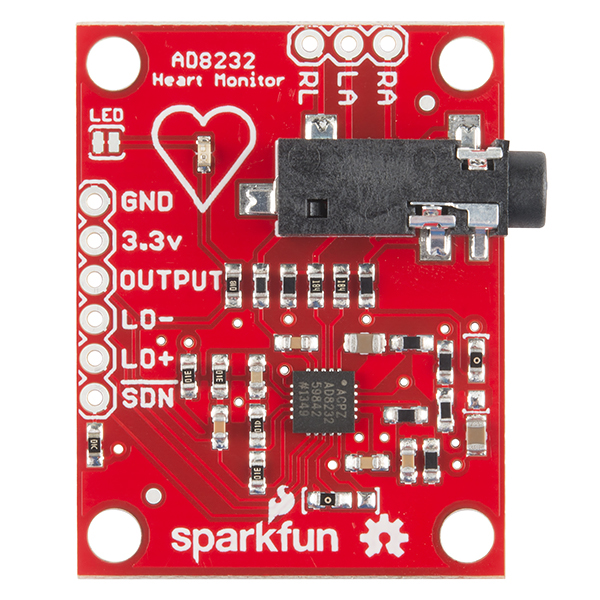
I’m looking for part AD8232 HEART Monitor
Can anybody help me?
FAQ: Where can I find “specific part” has some information about locating and asking for Fritzing part files for parts and components. This is a Sparkfun board, so that makes some things easier. Sparkfun provides Fritzing files for a lot of their parts and boards. Many are already in the core parts library. This one does not seem to be there, but both AD8232 product and AD8232 Heart Rate Monitor Hookup Guide pages include a link (under documents and resources) to the AD8232 Github Repository. That includes a Fritzing sketch file. The part can be exported from that, although in this case the schematic view is broken. It appears to have been cloned from a generic IC, but something is not linked up correctly. That repo also contains the eagle board files, so eagle2fritzing provides another way to create a Fritzing part.
I have not been able to get eagle2fritzing to run in my environment (WINE on linux), but I’ll have a look at what is wrong with the part in the sketch.
I just ran the brd file through eagle2fritzing so a proper part should be up in a while.
Edit: the github part is in better shape than the eagle2fritzing output, so I’ll clean it up and replace schematic with something more correct.
Peter
@vanepp Here are breadboard and pcb images run through my cleanup process. Icon is the same as breadboard. I seem to have wiped out a fill color somehow. Watch out for the connector sequence. The starting part had connectors 1 through 8 and 10, instead of 0 through 8. Not changed in these svg files


There are more problems than that. Breadboard is set to px and looks to be 90dpi Inkscape and so is mis scaled in current Inkscape. With the eagle2fritzing svg that was obvious and correctable. I’ll check pcb against the eagle2fritzing output as well.
Peter
I saw the px units, but had not got far enough to fix it. Fixing is easy. Just locate a pair of connectors with known spacing, use the number of svg pixels difference to calculate the scaling factor, then change the svg header element height and width attributes to match.
Easy to do with a text editor. Maybe more difficult with Inkscape.
I’ll have to try this. Inkscape is much more complex because it wants to readjust all the elements (and doesn’t like them grouped), it also tends to change circles in to ellipses due to floating point roundoff.
Peter
OK here is an improved version of the part on the Sparkfun site:
Sparkfun-AD8232-HeartRate-Monitor.fzpz (15.2 KB)
Peter
Here is an example using the breadboard file upload from the previous post.
<circle id="connector8pin" cx="1.2785" cy="12.112" r=".7239"/>
<circle id="connector10pin" cx="1.2785" cy="14.652" r=".7239"/>
<circle id="connector7pin" cx="1.2785" cy="9.5723" r=".7239"/>
Assuming those are 0.1in apart:
14.652 - 12.112 = 2.54
12.112 - 9.5723 = 2.5397
25.4mm per inch is pretty ‘standard’, so it looks like 2.54px per 0.1in. Then, from viewbox pixel values:
<svg xmlns="http://www.w3.org/2000/svg"
width="126"
height="105.95"
version="1.1" viewBox="0 0 35.56 29.901">
35.56 / 25.4 = 1.4
29.901 / 25.4 = 1.1772047244094488
Set the document dimensions:
<svg xmlns="http://www.w3.org/2000/svg"
width="1.4in"
height="1.1772in"
version="1.1" viewBox="0 0 35.56 29.901">
![]()
To get that to display properly on upload, I had to remove the “1x1” pixel size the forum software inserted. It seems to want to treat the “1 inch” as 1 pixel, but ‘fixing’ that is just a matter of removing the “|1x1” from the generated link. Or replacing it with something “reasonable”. Like 140x118 to make it a (very) little bigger, and keep the aspect ratio.

EDIT: That fudge with the link for display does NOT affect the file itself. A download will be correct, not rescaled in any way.
Thanks.its really great help for me.
FYI - I’m not suggesting you build this instead but, perhaps worth consideration…
I made several Pulse Rate monitors using variety of sensors from homemade with IR, LED’s, OPAmps…etc. All were a good bit of Fun and all required dialing-in.
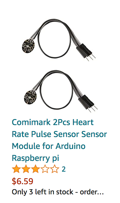
When I finished, I tried out some sensors from Amazon and decided because (at the time) they were only $3, it made sense to buy a box of them and forgo making my own (for about the same cost).
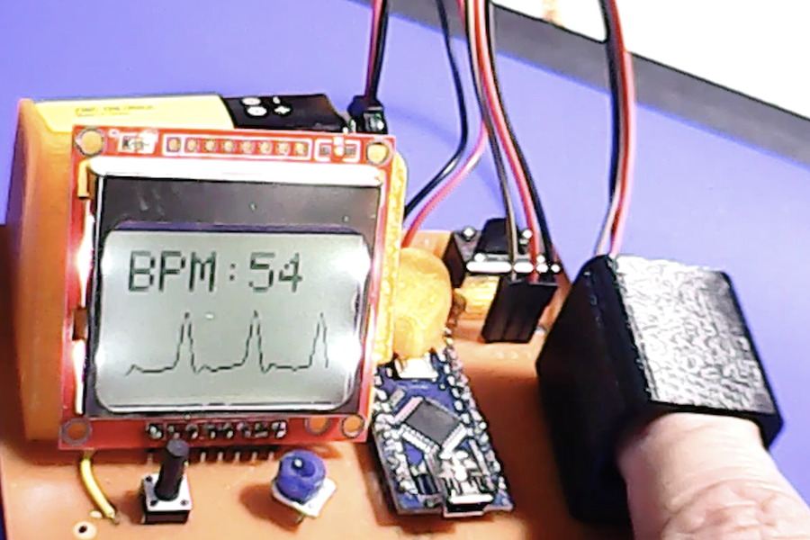
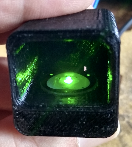
The units I bought (3 yrs ago) are TooGoo brand and there are several clones available (from a few dollars to rip-off prices). Screenshot… I made a 3D-printed enclosure for the sensor. Screenshot
I designed the electronics with Fritzing (that’s why I’m posting here) using Arduino Nano’s. Also used Nokia and TFT displays but prefer the Nokia 5110 INK LCD.
I use the “Pulse Sensor Playground” library for Arduino.
Fritzing file and Screenshots below… Yes, my pulse really is low 50’s bpm.
Pulse1_wTooGoo.fzz (47.1 KB)