About the parts submit category

Ethernet Module W5100 mini
W5100 mini.fzpz (21.6 KB)
i have modified the standard module in fritzing and create module w5100 mini that is easily find on ebay or bangood.
this is my first part…so if you have suggestion please upgrade that…

i try to make it double face xml., but in this mode i can’t get correct message when i import that in fritzing.what is wrong?help please.
i attach svg here:

hi i’m new here and i need some help, i need a relay ky-1 and i don’t find it

Parts for

  • EBYTE E73-2G4M04 bluetooth module
  • MOLEX KK 10 pin PCB connector
  • TAG CONNECT TC2030

Hi!
I don’t have any experience with .svg files, but my friend made me some files representing the Elechouse version of the PN532 for me to use for a school project. I have searched quite some time for this part and found that other people have also searched for this. It is probably far from perfect, so I suggest that someone updates and reposts it, but it does the job for me and I hope that I can make other people happy with it:) Many thanks to Wesley!

PN532 Elechouse RFID NFC Module V3PN532 Elechouse RFID NFC Module V3.fzpz (30.0 KB)

1 Like

H-Bridge L298N Modified

image

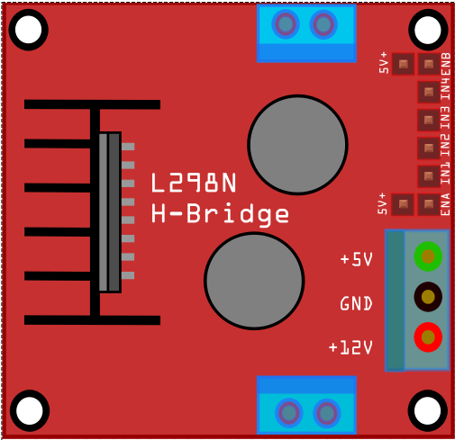
Breadboard+Icon+PCD+schematic all Working.
(Manoel Silva Filho - august,15,2020)
H-Bridge L298N.fzpz (22.4 KB)

Hello everyone. I need the STOCKO connector model designed in Fritzing so that I can import that model and use on bread board. Check the attached image. I need models of these two connectors on Fritzing.

I need following connectors
1- Stocko Connector 8 pins
2- Jamma Connector 28 x 2 pins

Please let me know if anyone can design these connectors.

Thanks

I just started fritzing and I needed a surface mount 16F628a chip. There wasn’t one in the library so I made one. Do I submit the part here? If so, it is attached.PIC16F628a.fzpz (9.8 KB)

I created a LM75 part that was missing in Fritzing. Attached.Temperature Sensor - LM75.fzpz (8.8 KB)

HT46R47 (A/D Type 8-Bit MCU)
DIP-HT46R47.fzpz (7.2 KB)

My first attempt at modifying the generic IC in Fritzing. I hope it could be useful to someone else.

Welcome aboard! Your part has a few issues. The most serious is that the pcb layout isn’t SMD and the part is. Here is an improved version with the following changes:

breadboard:

Convert to an adapter board that converts from SMD to .1in DIP spacing which is typically how SMD parts are represented in breadboard in Fritzing.

schematic

replace completely with one made with the Inkscape Fritzing extension which produces a schematic which meets the graphics standard (this is strictly cosmetic, the original would have worked, just doesn’t meet the standards.)

pcb

replace the footprint with a SMD version (and modify the .fzp file to remove the copper0 layer from pcb to make an SMD part!) This part has a new moduleId and thus will load along side your original part for comparison.

LM2731-improved.fzpz (4.6 KB)

Peter

Thanks Peter! I was aware about the SOT23 issues, and thought those were corrected already, but the rest was new :slight_smile:

Edit: @vanepp , I am struggling to find a guide on the correct layers (and their purpose, so what should be placed where) for SMD parts, do you happen to have one?

New try for another part: TC1108 3.3V Voltage Regulator by Microchip, Microchip TC1108-3.3VDBTR
TC1108.fzpz (6.7 KB)

The part file format document available here has the layouts

The difference between a through hole and a SMD part is that that SMD part only has the copper1 layer in pcb view where a through hole part has copper0 as a child group of copper1 and the copper appears on both sides of the board. An older format that had separate copper0 and copper1 layers (but for through hole the pads had to appear on both copper layers) is still supported and is sometimes useful for doing odd things. This tutorial series may help as well, as it describes how I make parts by editing the files themselves.

Part creation howto part 1 breadboard and pcb

As well you may want to change to the parts-submit forum category as posts here in About the parts submit category are not show as new posts in the forum (I expect there is something special about this particular topic) so most people won’t see the posts. I only came across it because the tool bar said there were unread posts even when there didn’t appear to be any. Clicking on it took me here.

Peter

Schematic is incorrect. Connector1 and connector2 are reversed which makes the schematic connection wrong (possibly in the original part you cloned from.)

Here pin 2 is labeled as ground which is correct, but hovering on the pin indicates that it is Vout which isn’t correct. That is because the .fzp file has the schematic pins reversed (FrtizingCheckPart warns about this like this:

Warning 13: File
‘part.TC1108-3.3V_f575382ffd5e554162f3290a17ddeb9a_1.fzp.bak’
At line 58

Value connector1terminal doesn’t match Id connector2. (Typo?)

Warning 13: File
‘part.TC1108-3.3V_f575382ffd5e554162f3290a17ddeb9a_1.fzp.bak’
At line 58

Value connector1pin doesn’t match Id connector2. (Typo?)

Warning 13: File
‘part.TC1108-3.3V_f575382ffd5e554162f3290a17ddeb9a_1.fzp.bak’
At line 86

Value connector2terminal doesn’t match Id connector1. (Typo?)

Warning 13: File
‘part.TC1108-3.3V_f575382ffd5e554162f3290a17ddeb9a_1.fzp.bak’
At line 86

Value connector2pin doesn’t match Id connector1. (Typo?)

which is caused by this in the .fzp file

connector0 is correct

  <connector name="Vin" id="connector0" type="male">
    <description>Vin</description>
    <views>
      <breadboardView>
        <p layer="breadboard" svgId="connector0pin"/>
      </breadboardView>
      <schematicView>
        <p layer="schematic" terminalId="connector0terminal" svgId="connector0pin"/>
      </schematicView>
      <pcbView>
        <p layer="copper1" svgId="connector0pad"/>
      </pcbView>
    </views>
  </connector>

but the pin numbers are backwards in connectors 1 and 2 in the schematic layerId

  <connector name="GND" id="connector1" type="male">
    <description>GND</description>
    <views>
      <breadboardView>
        <p layer="breadboard" svgId="connector1pin"/>
      </breadboardView>
      <schematicView>
        <p layer="schematic" terminalId="connector2terminal" svgId="connector2pin"/>
      </schematicView>
      <pcbView>
        <p layer="copper1" svgId="connector1pad"/>
      </pcbView>
    </views>
  </connector>

connector2 in the schematic layerId should be connector1 to match its definition and be correct in schematic.

Peter

Hi,
I created a “RBA3 Control Unit” for a sliding gate.RBA3 Control Unit.fzpz (1.0 MB)
example circuit Smarthome_gate_drive.fzz (1.1 MB)

Johannes

First off you would be better to post this in a post rather than as a reply to this About post. The reason is here this post does not show up as a new post except in the tool bar and thus many people will miss it. Then while it is overall a decent job it has a few issues. Breadboard is typically life size. This appears to be about 1/10 life size (2cm instead of 22cm wide for instance. That isn’t deadly but also isn’t common. As you see it looks a little small connected to a 0.1in header:

although it works fine. As well in schematic you are missing terminalIds on all but the first two pins. That causes the pins to not be on 0.1in boundaries and the pins to connect to the center of the pin for the ones without terminalIds like this:

the first two pins circled in green are correct, the rest need terminalIds added to be correct.

Peter

Hi,
thank you very much Peter see new post:

regards
Johannes

Hey everyone! Please check out a part I did very hastily and be sure to provide any feedback if you want :smile:

ATmega328A-Fritzing
the link above is for my github btw

For starters there is already a ATmega328 in core parts so you are reinventing the wheel. After that your part has a number of problems: In breadboard the chip size is incorrect (it should be 0.3in wide not 0.4)

schematic lacks a proper schematic layout

and pcb is a 40pin 0.6 wide chip and the pins are incorrectly specified.

These two tutorials on making parts apply to the current version of Fritzing (most other are for older versions)

Peter