8 typ-K thermocouple throgh Max31855 module to Arduino Mega 2560

Hello all , i am totally new in all this . i have no background in electrical or coding . i am attaching my circuit which i made in fritzing . can someone tell me the my connection are right or wrong. if i will do it in real then every thing will be ok?.

i am planning to connect 8 type k thermocouples through 8 max31855 module to the arduino mega 2560. i am attaching here picture .

here is my thermocouple details.

here is my max31855 module details.
MAX31855 Module + K-Type Thermocouple Thermocouple Sensor Temperature ‑200ā„ƒ~1350ā„ƒ Thermocouple Thermometer and Probes

Your best bet is to upload the Fritzing Sharable Sketch (.fzz) file so that we can help you…

Final Thermocouple.fzz (61.0 KB)

Thanks!
I’m halfway done fixing up the schematic. It’s getting ;ate at my side, but I’ll continue tomorrow

1 Like

okay , thanks a lot . it will be a very helpful for me …

Hello
is there any update for me ?

thanks a lot

Sorry for the late reply😄

Lately I realised a larger problem – the thermocouple operates at 3.3V logic levels, while the arduino mega 2560 operates at 5V logic levels!

I’ve never dealt with 3.3V logic levels before, (or rather very rarely) so I have no idea how to connect it to an arduino.

If anyone knows, please post! Otherwise @js13ropa you should ask the folks at adafruit for help here…
https://forums.adafruit.com/viewforum.php?f=8&sid=7c05a6a928ba537bcb46dc7a526b0e51

Then he needs to use a level translator (there are a bunch around, do a google search for ā€œfritzing part level translatorā€ to find them) to translate the 3.3V signals to and from 5V. If they are input only (not output to the 3.3V interface) it will usually just work as is. Driving a 3.3v input wiith 5V will generally damage the 3.3V part.

Peter

True, for me I normally use BSS138 logic level converter

But only has 2 channels. I mean, theoratically, you can lay out multiple logic levels (just that I’ve never tried doing that before!)

That said, here is my example with BSs138 Logic Level Convertor.

Thermocouple-incomplete.fzz (24.2 KB)

I’s getting late at my side, I can only help you out tomorrow. Good Luck!

Edit: I’m done, here’s my completed sketch
Thermocouple-improved.fzz (51.9 KB)

Note:

  • I’m a bit busy this week, so I did not complete the schematic view
  • Since the arduino is reading the thermocouple sensor, I think data is being transferred from the module to the arduino (i.e. 3.3V to 5V). If I’m wrong just let me know, I can fix the sketch. It is not to difficult to fix.

Edit 2:

Goodness Gracious, I almost forgot to put in 2 thermocouples
Thermocouple-completed.fzz (53.2 KB)

Hello thanks for help

still have questions if i will use TXSO108e logic converter which has 8 channel so it means for my applications i need only 2 module of this right ? .

and as you designed the sketch in which why you connected 3VO not vin ? .

Well I usually connect my wires to 3.3V (and not VIN) to my 3.3V electronics, so I applied the same logic and connected it to the 3.3V pin

I suppose so

Do you need the Fritzing sketch with the TXSO108e logic converter? If so I can create one (just that I’m busy now but I will be able to complete by the end of this week)

i am going to use this

Aihasd 10pcs 4 Channel IIC I2C Logic Level Logic Level Converter Bi-Directional Module 3.3V to 5V Shifter for Arduino : Amazon.de: Electronics & Photo if i will phase problem then i will let you know thanks

The Fritzing part here

should do for this module.

Peter

79b582844704aed86ca8c74183f0565c0c5e04e4_2_690x261

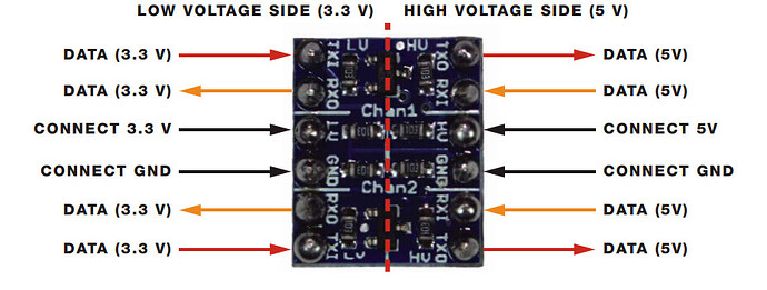
in this example used this logic level controller where i think connection 5 v at HV and 3.3 v at LV and from max 31855 spi pins throgh TXI at lower vvoltage side channel . i mean in this above photo where mentioned red color line .

so my question is i am using this logic converter which has following pins HV GND LV act same as above example here also i have to connect spi pins from max31855 to the LV1 and Lv4 . i mean i have to do same coonnections as it desiged above wiring ? .

here given LV1 act as TXI , LV2 act as RXO , LV3 as RXO , LV4 as TXI and so on . ?

What logic level convertor are you using? Or is it also BSS138 too, just that it is another variant?

Aihasd 10pcs 4 Channel IIC I2C Logic Level Logic Level Converter Bi-Directional Module 3.3V to 5V Shifter for Arduino : Amazon.de: Electronics & Photo this one

While I’m not entirely sure, I guess it’s the same (bi-direction, HV and LV1, 2, 3, 4 are sifnal pins, LV connects to 3.3V Power while HV connects to 5V power