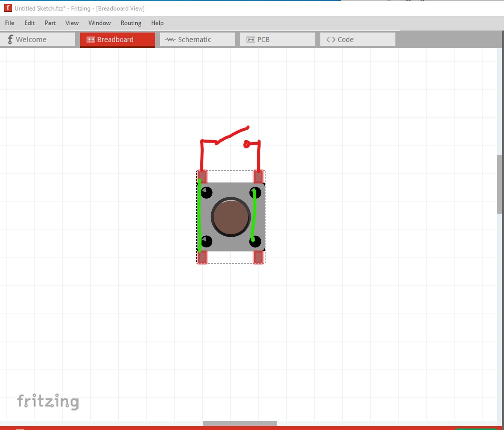
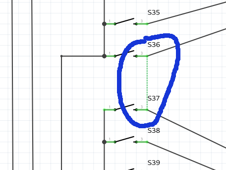
Your circuit is not wired correctly. If you left click on a connection all pins connected to that net will light yellow. Here is a single switch with no connections which shows the two right pins connect together:
The two left pins are also connected together but not to the right pins so they don’t light up.Note on this next image that all pins on the switch are shorted together and thus I don’t think this circuit will work as it stands.
Assuming you also have a standard midi interface hooked to the Arduino (there is none in your sketch), you can use a library to send midi commands. My first search hit Midi Library. The documentation link from there points to the repository on github, and the readme contains examples.
Simply sending a note on key press is not going to be “full” midi. Midi includes “velocity” information as well as the note.
I assume you intend a ‘matrix’ scan, to determine which key (or maybe keys) are pressed. Don’t forget to ‘debounce’ the keystroke readings.
I normally start with the schematic view, instead of breadboard. With my background, that is easier to verify for correctness, then use the ratsnest lines to wire up the breadboard.
You are using a mega. With the number of pins being used, an Uno would be plenty for this. Depending what else (like that midi interface) is to be connected to the same Arduino.
With the general way your sketch is wired, you are trying to have one of 5 (octave) sense pins go high (only) when the shift register output matches the single note key being pressed. The 10K resistors you have are not setup correctly for that. The ‘sense’ lines need to go directly to the Arduino pins. As setup, the sense pins are being held low all of the time. The pull down resistors may not be needed at all. The pinMode() function can be used to enable an internal 10K pullup resistor for input. Then detect a key press as low instead of high.
If you could use 12 digital input pins, one per note, then you could use a single shift register to walk across the 5 octaves. Instead of 5 input pins, one per octave, plus 2 shift registers to walk across the 12 notes. More pins, but only one shift resister.
Are you at all interested in detecting multiple keys pressed at the same time? That would need a different matrix scanning structure.
Thank you for your answers.
I use a computer as a virtual instrument, so I use USB as a MIDI output.
I was inspired by this forum to make my sketch: MIDI keyboard - code for matrix - Programming Questions - Arduino Forum
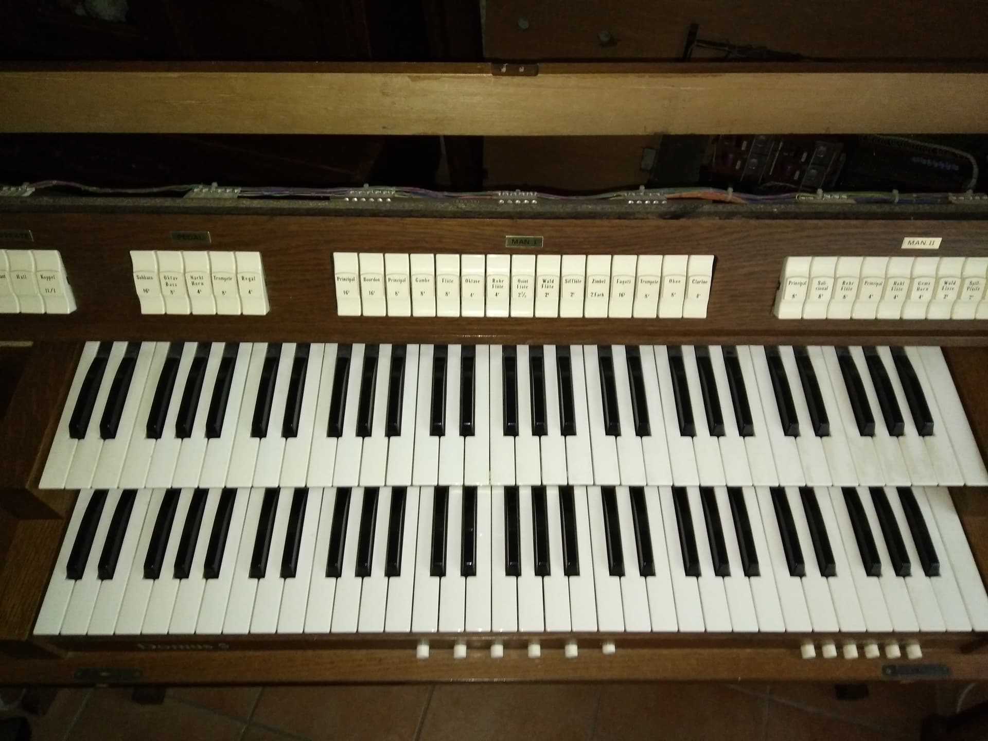
My keyboard has 61 keys, it starts with a C and ends with a high C (the first note of the sixth octave)
My organ has two 61-key keyboards, I intend to use a single arduino mega to matrix the two keyboards.
Of course I want my two keyboards to be polyphonic and to be able to play several keys at the same time.
The original instructable for that project was based on connecting to the existing cable inside the keyboard. No switches needed. It just does the scans across the matrix (after figuring out which wires on the cable correspond to each key press). Does your keyboard have something similar, or are you going to try to put a push button switch under each key, where it will be activated when a key is pressed?
Done correctly, the matrix scan can be polyphonic. A normal computer keyboard sends “scan codes” to indicate each key press and key release (implementation details different for ps2, usb, high speed usb keyboards). That is effectively what you want to create. The “driver” for the keyboard, that detects switch open and close events, and outputs scan codes. Where the scan codes are the midi on and off commands for the corresponding note.
So (after hardware working), the code needs to set up (and remember) a “state” (on or off) for each key. That can be done as an array. Or more compactly as bits. Then the scan process compares the current state of a key with the previous in memory. If it changed, send the appropriate note on or off command, and update the state in memory.
For initial development and testing of the scan portion, you can just write “key up” and “key down” messages to Serial, with (first) matrix row and column for the key. When that is working, replace the row and column values with actual note and octave. With that working, change to sending the actual midi notes.
The midi portion of the code can similarly be tested separately. Starting with a simple scale that covers the range of the keyboard, then advancing to some cords. With both the keyboard scanning and midi playing working, it (just) needs a lookup from matrix address to midi note. Technically that is a 2 dimensional (row and column) lookup, but that can be reduced to a 1 dimensional lookup by combining the 5 octaves with 12 notes each, into a single integer. Multiply the note key number (from 0 to 11) by the octave number (1 to 5) to get a number from 0 to 55. Although you said 61 keys. I do not know where the other 6 are coming from with your description.
Reminder to check what “key bounce” means. You probably do not want multiple key up, key down sequences sent for each press and release.
I use the wires already present on my keyboard: 1 common and 1 other wire for each key. With the keys of my organ I will be able to apply the midi protocol: note on / note off only. Because it is not a dynamic keyboard. I haven’t found any other equivalent for the organ keyboard keys than the S15 switch buttons in fritzing.
With a simple program and without matrixing my arduino board, I have already managed to get a midi signal and play a virtual instrument on my computer. But it requires a lot of wires plugged into the arduino board. Whereas with matrixing there are not so many wires needed and only one arduino board is enough.
I send you the photo of the keyboard.
For the moment I set myself the objective of midifying only the keyboard with note on and note off in digital pin.
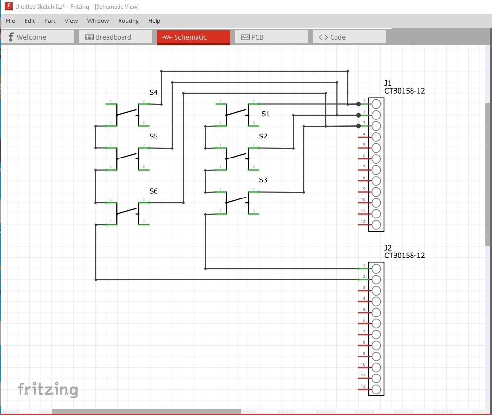
I think we need a drawing of how the switches on the keyboard connect to the 12 pin screw terminals. As I understand this the switches are on the organ keys and connect (in some currently unknown manner) to the 24 pins of the screw terminals. In that case the switches in Fritzing are not needed, the connections to the screw terminals are enough. We do however need to know what the connections to the screw terminals look like in terms of how the switches connect, preferably in schematic view like this (note this is only one way the switches could connect, there are several others as well and we need to know which one applies to your case!)
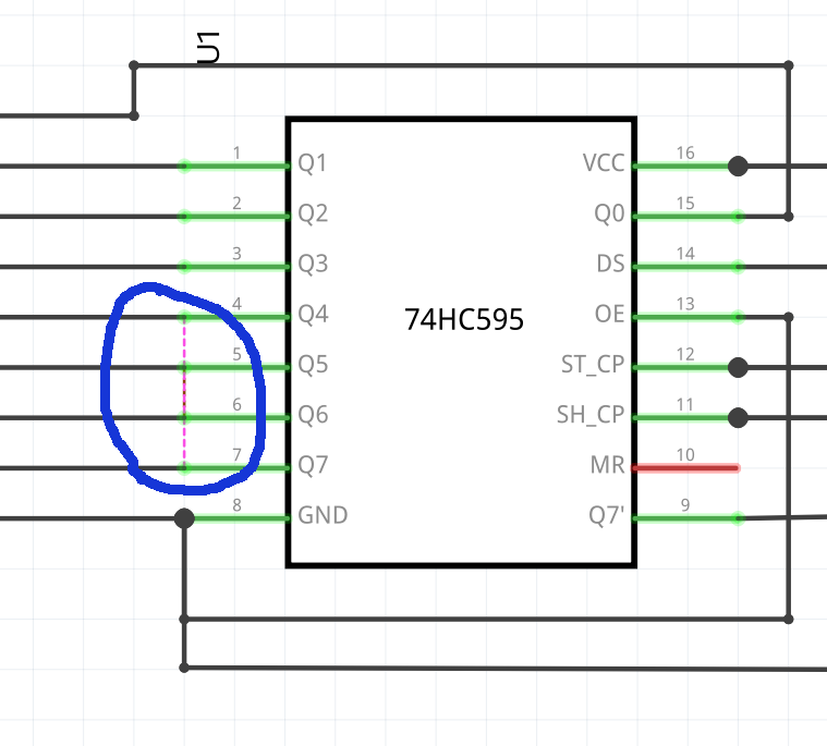
In this case only 1 pin at a time on J2 (the bottom screw terminal) can be driven, all the other pins need to be not driven either high or low (which isn’t possible with the 74hc595!) What is wrong with your current sketch is that the switch has two terminals (which are connected together in the vertical direction) for each pin on the switch. In breadboard it matters which terminals you connect to. The way you have them currently connected shorts the switch terminals together and won’t work. Here (in schematic) both left pins marked 1 connect to each other as shown, the 2 right pins are on the other side of the switch (and also connect to each other.) The same is true in breadboard. Here the green indicates an internal connection between the two pins and the red indicates where the switch connects across the push button.
Depending on how the switches in your organ keyboard connect to the terminal strips, you need either open collector drivers (which the 74hc595 doesn’t have) or diodes to prevent multiple simultaneous key presses from producing incorrect results. We won’t know what exactly is needed until we understand how the keys from the organ connect to the screw terminals. So a drawing that relates the switches on the organ’s connection to the screw terminals is the first need.
I did not make the right choice by taking the push button. I should have taken the momentary switch -2. (the two look the same, I made a mistake)
Indeed the keys of a midi keyboard come back and never feel depressed when you no longer press it:
Midi on = key pressed
midi off = key not pressed
The keyboard key is nothing more than a simple switch that the mechanism of the key allows to remove the contact when you no longer press it.
Without the matrixing, just program the arduino board to send the midi signal and wire the switch on the arduino board to GND at one of the terminals and a digital PIN at the other terminal.
Here is the program that allowed me to test the midi signal: ` #include <MIDI.h>
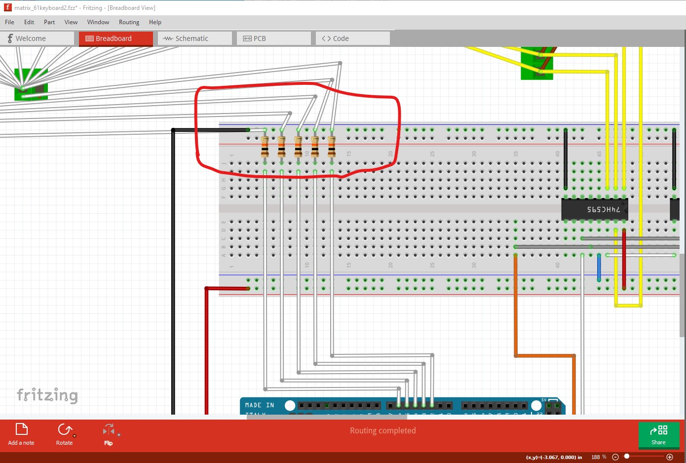
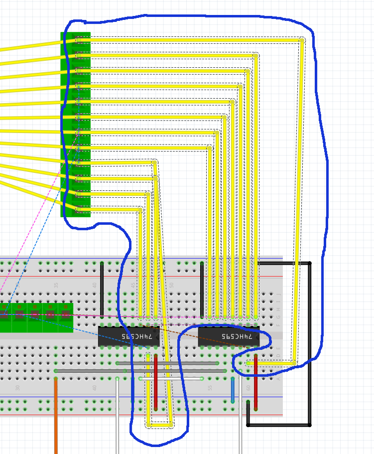
Off the top, this is wrong. Assuming the pins on the Mega are supposed to select which bank of switches are selected, this does not do that. All banks of switches are connected to ground. I have some suspicion the white wires in the red circle should be connected to the white wire on the resistor, but can’t say for sure because it is unclear how the switches on the organ are arranged. I am however pretty sure this is broken and won’t work.
It will likely also have problems detecting multiple keys pressed at the same time (I expect it won’t see any key presses in its current state) even if the white wires are moved.
I assume from that, plus your diagrams showing matrix style switches, that you mean that for a single octave there is one common wire plus one for each key in the octave, but that same wire is used for (for example) the “c#” key in each octave. Each octave has a different “common” wire. Which would give connection something like the diagram below. I used the sparkfun push button for this, which (in schematic view) shows a simpler switch symbol. I also used net labels for the individual keys to simplify the diagram. All of the label symbols, with the same text label are wired together. Assuming this is accurate, then as @vanepp said, the switches themselves are not needed in the main sketch. All that is needed is the terminal strip with labels to show which pin is connected to a key, and which are common the octaves. From that we can work out the wiring and logic needed for a full polyphonic scan of the matrix. What (I expect) is needed is to scan both the keys and the octaves. Everything defaulting to “high impedance” with one “key” line set high, and one “octave” line set low, plus a separate sense pin to detect when the switch for that combination is closed (possibly 5 sense pins, one for each octave).
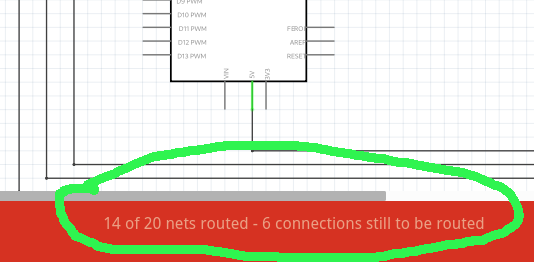
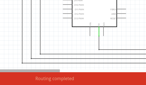
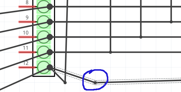
The switch wiring on the schematic view looks correct, and equivalent to what I did with the net labels. However, the breadboard view does not match the schematic. That is shown by (on schematic view) that there are connections still to be routed.
That says that there are connections between nets (nodes) on another view, that do not currently exist in this view. So something is wrong or not finished yet. The specific “still to be routed” cases are shown as ratsnest lines (dashed line). Those are each a case where there is a connection (wire) on a different view that joins the nets that the pins are part of.
I showed that by deleting those breadboard wires, then back on schematic view, routing is completed. Those breadboard wires are creating new connections that do not exist in the schematic.
Other comments, but not specifically problems, in the next post
For this, I started by deleting the breadboard wires shown in the previous post, to get to better working state.
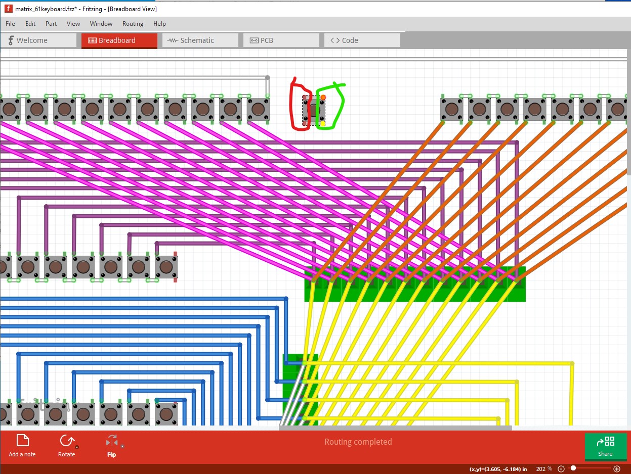
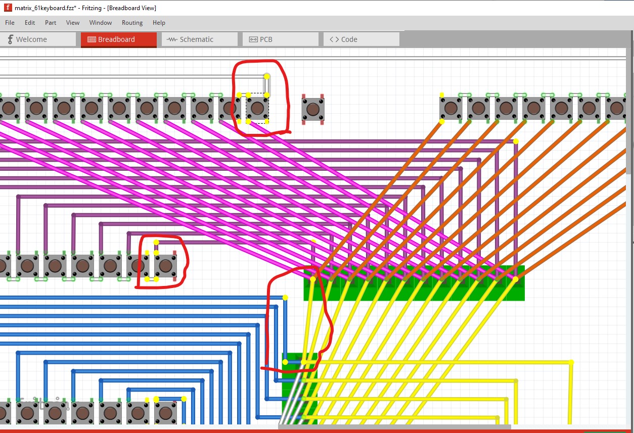
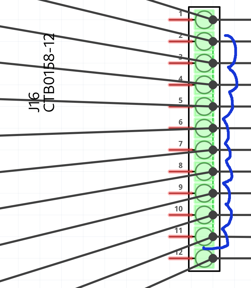
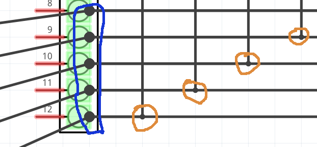
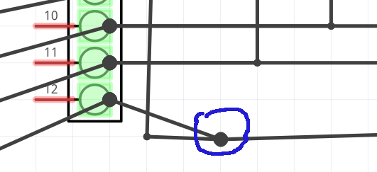
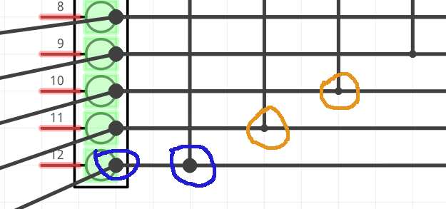
I mentioned in a previous post in this thread that there can be problems (at least confusion) if wires are drawn on top of each other. They are not really connected, and it can be difficult to tell exactly where the wire is ending. Without either moving the wire, or clicking an connection in its net to see all of the connections in the net. You have done that for the matrix of connections for the key switches. In the snapshot below, the connections are circle in blue. The orange circles are bend points in the wires, NOT connections.
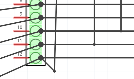
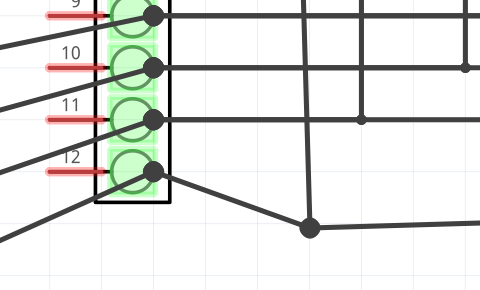
That is shown below by dragging the bend point, which makes the separate wires visible. The ends of the wires both go to the same connection point, so that are connected. But that can not be seen with the original layout.
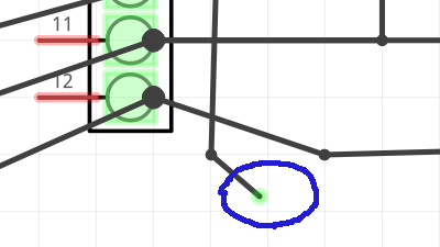
It is not possible in Fritzing to connect the end of a wire to another wire by just ending the wire on top another wire. However, you CAN end a wire at a bend point in another wire. After moving the wire as above, I create a bend point in the horizontal wire by dragging the middle of it down.
Now the end of the previous wire can be moved off of the terminal block connection point, then on to the new bend point, creating a connection. Then delete the now unneeded bend point in the first wire, and move the connection point back to where the original bend was.
Creating the bend point first, before adding the second wire makes this simpler. It is not necessary to ‘fiddle’ to pick up the end of the (correct) wire from the connection point.
I expect that the switches on the keyboard come out to a single connection point for the common octave lines, and another set of connections for the keys within an octave. Not each octave to it’s own separate block, which is then connected to the other blocks. Using ideas from the previous post, here are a few small variations on ways to lay that out. Without using the net labels that I started with. This is for the keyboard only. No arduino, shift register, or sensing.
The point is that this “ends” at a pair of terminal blocks, which are all that would need to be included in a sketch to define the switch sense logic. The switches themselves are “assumed” to be at the other end of the terminal connections, without needing to itemize them in the sketch. The keyboard is external to the midi project electronics. All that sketch needs is a matching pair of terminal blocks, preferable with labels to show which pin is “key c” etc, and “octave 1” etc. It only needs to know the definition of what is on each of the terminal block pins.
Initially have something like these sketches is helpful, when figuring out what key and octave are connected to which pins. But later, it just makes the schematic diagram more complex than it needs to be. It also makes the breadboard view really messy. When doing the breadboard for the project, you are not really connecting to all of the switches. Only to the terminal blocks that the switches are already connected to.
You will have to figure out and tell us how the 61st key is wired. The basic matrix is 12 keys per octave by 5 octaves, or 60 keys. Is that last key on another octave? A 13th key on one of the existing octaves? Completely separate (needing 2 more wires to connect)? None of the information so far provides any way to tell. We do not have your keyboard, or any documentation for it.
This is not really ready for coding yet. You still need to define the hardware (electronics) that will allow polyphonic sensing of the key presses. I do not think the simple shift register plus individual octave pins is enough. Definitely not with the way the resistors are shown so far. You need to define how the hardware (driven by the code) will be able to detect when “key c” is pressed in 2 different octaves, as well as 2 keys in the same octave. Or 2 in one octave and 2 in another. What will the signals (voltages) be, and where will the sense line(s) be? A schematic can help trace the voltages/currents, but you do not need the full matrix to do that. Figure out how to do it correctly with a 2 by 2 matrix of switches, then expand to more afterwards. A 2x2 matrix has 16 unique cases to detect: no keys pressed; any 1 key pressed, one of 6 pairs of keys, 4 cases with 3 keys pressed, and one with all keys pressed. A schematic is not “required”. A description of what the control signals will do is enough. Along the lines of:
one key line is pulled high with all others pulled low and one octave drive line pulled low with all others in high impedance state (input mode instead of output) will leave the sense pin for the octave either high or low depending on the state of (only) the single key in that octave.
With details to match the circuit you are using. Note that my description implies 10 pins for the octaves. 5 to “drive” them, 5 more to “sense” them. Potentially, the “drive” could be from shift registers, but also note that my description has the “other” drive lines as high impedance (off, not high). So far, that is the “best” configuration I can think of. Research on “n-key switch matrix logic” might get a better solution. I see some circuits using diodes, but have not wrapped my head around how it works. Most of what I see looks like it only works with one key at a time.
Please excuse my misunderstanding of the wiring. I followed the instructions on this site but I don’t see where the error is: Add MIDI Port to Keyboard : 15 Steps (with Pictures) - Instructables
On the other hand, I find that the solution of a single key without matrixing plugged into an arduino pin is very good.
As for polyphony I think the command Serial.begin(38400) (or other baud rate) will work.
Indeed it works for the code without matrixing that I shared on this forum, and you can play several notes simultaneously. I think the number of possible polyphonic notes depends on the baud rate.
For information I use QJackCtl and Hairless Midi Serial Bridge in linux.
So far you appear to have missed (or at least not posted!) step 4 ( figure out the keyboard matrix.) After that the pull up resistors and wiring of the shift registers is incorrect and won’t work, but without knowing what the key wiring looks like (which only you can provide) there isn’t much that can be done to correct it as we don’t know how the keys are wired in the actual organ.
We can not “see” your wiring. All we can go by is latest sketch you posted. Which, as mentioned several times, has errors around (at least) the way the common octave lines (switches) and resistors are connected to the arduino. Look at step 8 in that instructable. The 2 schematics in the corner. Are you trying to use pull up or pull down? Your sketch is neither. From the instructable, the switch (octave line) ALWAYS connects directly to the arduino pin. Your diagram has the switch connecting THROUGH the resistor to the arduino. The resistor connects from the arduino pin to either ground or VCC, depending whether pull up or pull down is being used. In your sketch, 2 of the resistors are connected to ground, 3 are not. Those 3 are not connected to VCC either. Get that, and any other cleanup already discussed cleaned up, the post a new version of the sketch that we can then look at to see if there any other problems.
As said, we can not see your wiring (and a picture can be pretty hard to use to verify). So make VERY sure that the wiring actually matches the sketch.
As I said in an early post in the thread, I do not understand how this wiring will work for detection of multiple simultaneous key presses. If the shift register is ALWAYS outputing a 0 or 1 on every pin (one pin one wayt, the rest the other), then with the simple switch matrix shown so far, pressing 2 keys in the same octave will “short” those 2 pins on the shift register. That can be fixed by adding diodes to each of the key lines (on the side connecting to the shift registers). The instructable says that the keyboard may only work using pull up or pull down. That COULD be because the diodes are already in the keyboard, part of the switch matrix. If they are not there, you will need to add them to your circuit.
My quick scan of the instructable did not show it, but it is possible to detect the diodes when doing the resistance checks to figure out which keys are connected to each wire on the ribbon cable. Depending on the multimeter being used, you may need to change from resistance mode to diode mode. Some meters in resistance mode use so little current that a diode shows the same as an open switch, in either direction.